
Centrifugal cutterheads and mowers

A technology of lawn mowers and cutterheads, which is applied to harvesters, cutters, agricultural machinery and implements, etc. It can solve the problems of low cutting blade power and occupying a large space, so as to prevent fingers from getting close to the blade and reduce driving resistance Effect

Active Publication Date: 2016-08-17
ZHEJIANG YAT ELECTRICAL APPLIANCE CO LTD
View PDF7 Cites 0 Cited by
  • Summary
  • Abstract
  • Description
  • Claims
  • Application Information

AI Technical Summary

Problems solved by technology

Therefore, additional cooling equipment is needed for these devices, such as reaching a certain cooling effect by the wind force of the rotating blade, but due to the low power provided to the cutting blade in this trimmer, it is not enough to only rotate and cool through the blade; It is also possible to add a cooling fan, but additional power requirements are required for fan operation, and it will take up a lot of space

Method used


Image

  • Centrifugal cutterheads and mowers
  • Centrifugal cutterheads and mowers
  • Centrifugal cutterheads and mowers

Examples


Embodiment 1

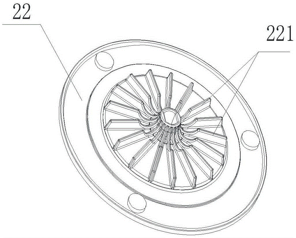
[0022] Such as figure 1 As shown, the centrifugal cutterhead includes a cutterhead body 22, the cutterhead body 22 is a disc, and the top surface of the cutterhead body 22 has several blades 221 with a certain height, and the cutterhead body 22 and the blades 221 are integrally formed. structure, the blades 221 are distributed in a divergent shape around the rotation centerline of the cutter head body 22 , and the blades are approximately perpendicular to the top surface of the cutter head body 22 .

Embodiment 2

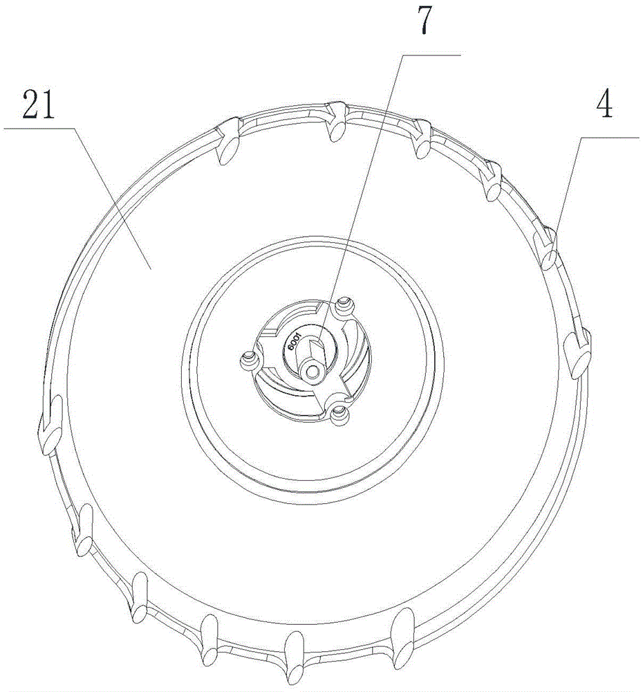
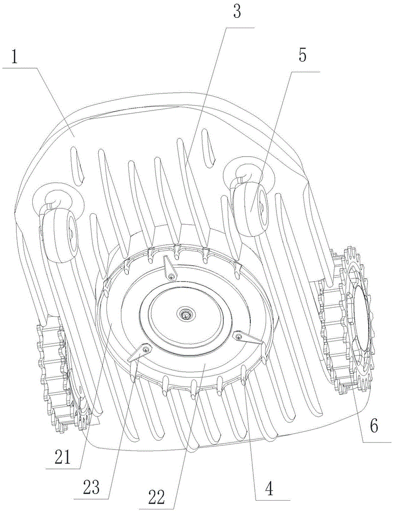
[0024] Such as Figures 2 to 6 As shown, the lawn mower includes a casing 1 and a blade assembly mounted on the casing 1. The blade assembly has a cutter head, and the casing 1 is equipped with a drive mechanism connected to the cutter head for driving the rotation of the cutter head. The disc is a centrifugal cutter disc as in Embodiment 1. The cutterhead frame 21 exposed to the bottom of the casing 1 is installed on the casing 1, the bottom surface of the casing 1 has a hole 12, the top of the cutterhead frame 21 has a cylinder 212 extending into the hole 12, and the cutterhead is positioned at the bottom of the cutterhead. Below the frame 21, the driving mechanism includes a motor 7 installed in the cylinder 212, and the output shaft of the motor 7 extends to the bottom of the cutter head frame 21 to be connected with the cutter head. The cylinder 212 extends into the hole 12 and is slidably matched with the casing 1 . The outer wall of the cylinder 212 is provided with a...


PUM


Abstract

Provided is a centrifugal cutter head, comprising a cutter head body (22); the top surface of the cutter head body (22) has a plurality of blades (221); the blades (221) encircle the centerline of the cutter head body (22) in a divergent distribution; the cutter head body (22) and blades are integrally formed as a single structure (221); also provided is a lawnmower. The blades are integrated on the upper part of the cutter head, such that when a lawnmower having the described cutter head is cutting grass, the control circuit board and electric motor inside the lawnmower circulate air for the purpose of cooling; at the same time, a difference in pressure is produced above and below the cutter head frame, creating microcirculation and discharging grass clippings and dust, thus creating protection from dirt and dust.

Description

technical field [0001] The invention relates to a centrifugal cutterhead for a lawn trimmer, especially an automatic, self-guiding, or self-supporting lawn trimmer and a lawnmower using the centrifugal cutterhead. Background technique [0002] Existing lawn trimmers have the problem of overheating of electrical components due to high cutting load, high ambient temperature or a combination of these two conditions during work. Overheating can affect the performance of electronic devices and batteries, especially lithium batteries. Automatic lawn This is especially true with trimmers. Lawn trimmers are typically outside in the sun most or all of the time, and in the case of lithium batteries, the electronics are often constructed to prevent product operation when the battery cells are above a certain temperature limit, in order to prevent permanent damage or in extreme cases catch fire. Therefore, additional cooling equipment is needed for these devices, such as reaching a ce...

Claims


Application Information

Patent Timeline
Patent Type & Authority Patents(China)
IPC IPC(8): A01D34/73A01D34/82
CPCA01D34/73
Inventor 郑亚平李信何志强
Owner ZHEJIANG YAT ELECTRICAL APPLIANCE CO LTD
Learn More