Lawn mower guards and lawn mowers

A protective device and lawn mower technology, which is applied to harvesters, agricultural machinery and implements, cutters, etc., can solve the problems of large resistance, potential safety hazards of the fence-type cover structure, and large labor costs, etc., and achieve reduction The effect of driving resistance

Active Publication Date: 2016-08-17
ZHEJIANG YAT ELECTRICAL APPLIANCE CO LTD
View PDF6 Cites 0 Cited by
  • Summary
  • Abstract
  • Description
  • Claims
  • Application Information

AI Technical Summary

Problems solved by technology

like figure 1 and 2 As shown, the existing protective structure is to set a fence-type cover structure formed by a plurality of connecting bars I03 outside the blade assembly 02 at the bottom of the trimmer casing 01, and the connecting bar I03 passes through the connecting bar II04 at the top. The unavoidable problems of this protective structure are: 1. The resistance of the trimmer is relatively large when it is working, and the automatic trimmer needs to provide greater power; 2. The protection range of the fence-type cover structure is limited, and the operator or When children are playing, their arms, arms, fingers, etc. can easily extend into the fence-type cover from the gap between the casing 01 and the ground and be cut by the blades. The structure of the fence-type cover has a relatively large safety hazard; 3. The fence-type cover structure, due to the long length of the connecting strip, is suspended in the middle and is only fixed at both ends. When mowing grass, due to the large resistance or when the cover touches the ground, the connecting strip is easy to break; 4. The fence-type cover The structure is installed on the casing 01 by fasteners such as bolts, which is time-consuming and labor-intensive, and the labor cost is high

Method used


Image

  • Lawn mower guards and lawn mowers
  • Lawn mower guards and lawn mowers
  • Lawn mower guards and lawn mowers

Examples


Embodiment 1

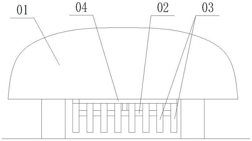
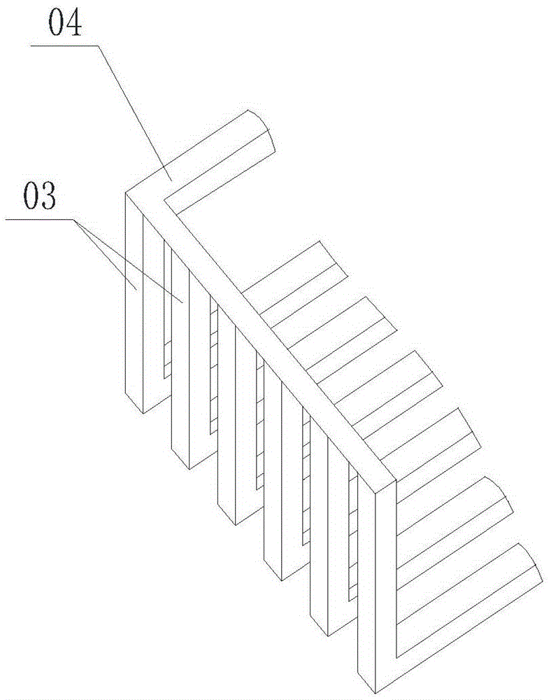
[0025] Such as image 3 with 4 Shown is an embodiment of the protection device for a lawnmower, wherein the lawnmower has a casing 1 and a cutterhead frame 21 that is installed on the casing 1 and exposed to the bottom surface of the casing 1, and the cutterhead frame 21 is provided with a Cutter 22, three uniformly arranged blades 23 are installed on the edge of cutter 22, drive motor is installed on cutter frame 21, the output end of drive motor is connected with cutter 22 and drives cutter to rotate, lawn mower protection device includes Some long lamellar ribs 3 that are arranged on the bottom surface of the casing 1 and some protective columns 4 that are arranged on the bottom surface of the cutter head frame 21; On the bottom surface of the shell 1, the ribs 3 surround the cutter head frame 21, and the protective column 4 surrounds the cutter head 22. The extension direction of the ribs 3 is consistent with the direction of travel of the lawn mower. Between two adjacent...

Embodiment 2

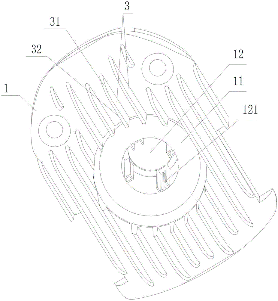
[0027] Such as Figures 3 to 5 Shown is an embodiment of a lawn mower, the lawn mower has a casing 1 and a cutter head frame 21 installed on the casing 1 and exposed below the bottom surface of the casing 1, the bottom surface of the casing 1 has a circular groove 11 The center of the circular groove 11 has a hole 12, the top of the cutter head frame 21 has a cylinder 212, the cutter head frame 21 is set in the circular groove 11, and the cylinder 212 extends into the hole 12 to slide and fit with the casing 1. The outer wall of the cylinder 212 is provided with a slider 213, and the inner wall of the hole 12 is provided with a chute 121 slidingly matched with the slider 213, so that the cutter head frame 21 can slide up and down relative to the casing 1, and a motor is installed in the cylinder 212. The output end of the motor is equipped with a cutterhead 22, and three evenly distributed blades 23 are installed on the edge of the cutterhead 22. The cutterhead 22 and the blad...

Embodiment 3

[0029] Such as Image 6 with 7 As shown, the difference from Embodiment 1 is that some or all of the ribs 3 on the bottom surface of the casing 1 are replaced by some protective columns 4 arranged in rows, and the arrangement direction of each row of protective columns 4 is the same as that of the lawn mower. The direction of travel during work is consistent, and there is a certain distance between two adjacent rows of protective columns 4 .


PUM


Abstract

Provided are a lawnmower protective device and a lawnmower; the lawnmower has a housing (1) and a blade assembly; the blade assembly is disposed below the bottom surface of the housing (1); the lawnmower protective device comprises a plurality of protective members protruding from the bottom surface of the housing (1); the protective members surround the blade assembly, and every two connected protective members are spaced apart. The protective members being arranged surrounding the blade assembly located on the bottom surface of the housing (1) of the lawnmower solves the problem of a large clearance between the ground and the bottom surface of the housing; the ribs also have the function of diverting grass during mowing, reducing drive resistance.

Description

technical field [0001] The present invention relates to a protection device for a lawn trimmer, especially for a rotary blade cutter of an automatic, self-guided, self-supporting lawn trimmer and a lawn mower. Background technique [0002] In an automatic lawn trimmer, a motor-driven blade rotates about a generally vertical axis. Traditional rotary lawn trimmers require protective structures around the blades to prevent injury to the user or others approaching the trimmer during operation . Such as figure 1 with 2 As shown, the existing protective structure is to set a fence-type cover structure formed by a plurality of connecting bars I03 outside the blade assembly 02 at the bottom of the trimmer casing 01, and the connecting bar I03 passes through the connecting bar II04 at the top. The unavoidable problems of this protective structure are: 1. The resistance of the trimmer is relatively large when it is working, and the automatic trimmer needs to provide greater power; ...

Claims


Application Information

Patent Timeline
Patent Type & Authority Patents(China)
IPC IPC(8): A01D34/82
CPCA01D34/82
Inventor 郑亚平李信陈凤梧
Owner ZHEJIANG YAT ELECTRICAL APPLIANCE CO LTD
Why Eureka
Try Eureka