A Cam Mechanism Research Instrument

A technology of a cam mechanism and a rack is applied in the field of teaching instruments, which can solve the problems of inconvenience for teachers to carry, difficult for students, and few teaching equipment and equipment, and achieves the effect of improving teaching efficiency and enhancing learning interest.

Inactive Publication Date: 2017-03-01
陈志昂
View PDF6 Cites 0 Cited by
  • Summary
  • Abstract
  • Description
  • Claims
  • Application Information

AI Technical Summary

Problems solved by technology

The basic principle of the cam profile design method Whether the cam profile curve is designed by the graphical method or the analytical method, the basic principle based on it is the inversion method. The transfer rule of the vice, the method of reversely calculating the profile of the cam, the disadvantage of this method is that it violates intuitive thinking, is complicated and difficult to understand, and is a major difficulty in teaching
[0004] Due to the lack of simple and effective "cam mechanism" teaching instruments, it is difficult for students to understand and learn this structure intuitively and effectively, and the existing cam teaching instruments have the following problems:
[0005] (1), the relevant teaching instrument of the various cam mechanism dynamic test benches that prior art adopts, floor space is bigger, is not convenient to place in classroom, more inconvenient for teacher to carry;
[0006] (2), most of the existing mechanical course teaching equipment is a virtual demonstration equipment based on a computer, which lacks intuition;
[0007] (3) There are few teaching equipment specially designed for the typical mechanical structure of "cam";
[0008] (4), the existing cam demonstration instrument only provides a given fixed displacement curve, and then analyzes the cam profile, and cannot study different and various displacement curves

Method used


Image

  • A Cam Mechanism Research Instrument
  • A Cam Mechanism Research Instrument
  • A Cam Mechanism Research Instrument

Examples


Embodiment Construction

[0059] The following will clearly and completely describe the technical solutions in the embodiments of the present invention with reference to the accompanying drawings in the embodiments of the present invention. Obviously, the described embodiments are only some, not all, embodiments of the present invention. Based on the embodiments of the present invention, all other embodiments obtained by persons of ordinary skill in the art without making creative efforts belong to the protection scope of the present invention.

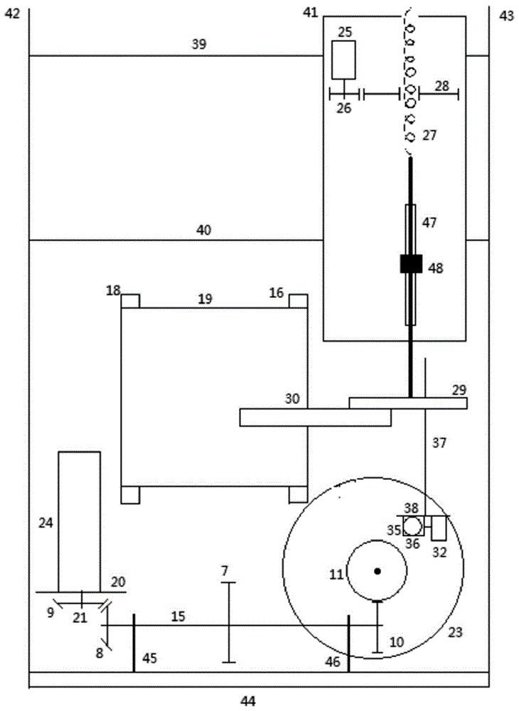
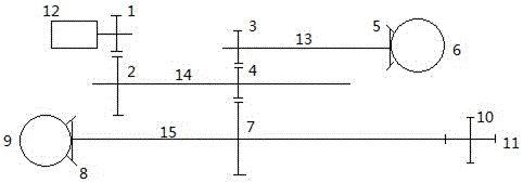
[0060] refer to Figure 1-10 , the present invention proposes a cam mechanism research instrument, comprising a frame composed of a chassis 44, a left column 42, and a right column 43, the bottom of the frame is provided with a first transmission shaft 14, a second transmission shaft 13 and a third transmission shaft 15 , the two ends of the third transmission shaft 15 are respectively supported by the first support base 45 and the second support base 46 on th...


PUM


Abstract

The invention discloses a study instrument of a cam mechanism. A push rod bottom board is arranged on the upper portion of a machine frame. The push rod bottom board is connected with the machine frame through an upper polished rod and a lower polished rod. A third straight gear set and a push rod assembly are arranged on the push rod bottom board. A driving gear of the third straight gear set is driven by a second stepping motor. The push rod assembly penetrates through a driven gear of the third straight gear set through a sleeve. The lower portion of the push rod assembly is provided with a brush component bottom plate. A linear array CCD is connected with a brush bottom plate through a linear array CCD installation board. The linear array CCD corresponds to a white cloth band. An installation rod is perpendicularly arranged on the brush component bottom plate. The brush bottom plate is arranged at the tail end of the installation rod. A sliding block with a clamp is arranged on the brush bottom plate. A brush is clamped on the clamp. The brush is in contact with a second disc or a cylinder. A steering engine on the brush bottom plate is connected with the sliding block through a crank connection rod mechanism. The principle of the cam mechanism can be completely and accurately shown and a good tool is brought for teaching of the cam mechanism.

Description

technical field [0001] The invention relates to the technical field of teaching instruments, in particular to a cam mechanism research instrument. Background technique [0002] The cam mechanism is one of the common mechanisms in mechanical design. Since the cam mechanism has significant advantages such as high indexing accuracy, good high-speed performance, stable operation, large transmission torque, self-locking during positioning, compact structure, small volume, low noise, and long life, the cam mechanism is used in various machinery, especially It is widely used in automatic machines and automatic control devices. The cam mechanism is a high-level mechanism composed of three basic components: the cam, the follower and the frame. The cam is a component with a curved profile, which generally rotates at a constant speed for the active part; the component in contact with the cam profile generally performs reciprocating linear motion or swings, called the follower, and th...

Claims


Application Information

Patent Timeline
Patent Type & Authority Patents(China)
IPC IPC(8): B43L11/00
Inventor 陈志昂张行姜扬帆闫业亮
Owner 陈志昂
Why Eureka
Try Eureka