Eureka AIR delivers breakthrough ideas for toughest innovation challenges, trusted by R&D personnel around the world.

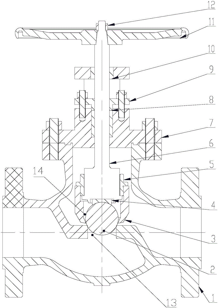
Stop valve with double automatic aligning and sealing assemblies

A stop valve, automatic technology, applied in the direction of lift valve, valve device, engine components, etc., can solve the problems of great influence on valve sealing performance, uneven wear of valve core and valve seat, poor valve sealing performance, etc., to achieve uniform Wear, improve sealing level, reduce the effect of machining accuracy

Active Publication Date: 2016-09-07
湖南西爱斯流体控制设备有限公司
View PDF7 Cites 0 Cited by
  • Summary
  • Abstract
  • Description
  • Claims
  • Application Information

AI Technical Summary

Problems solved by technology

[0004] However, the valve core sealing surface of most globe valves in the traditional technology is a conical surface, and the valve core is connected with the valve stem; when the valve is closed, the valve core cone is inserted into the conical hole of the valve seat, and the valve core and valve seat The coaxiality of the valve has a great influence on the sealing performance of the valve, because of the problem of machining accuracy, it is impossible for the valve core and the valve seat to be completely coaxial
Furthermore, due to the influence of the misalignment problem, the valve core and the valve seat are often misaligned, which leads to poor sealing performance of the valve, uneven wear of the valve core and valve seat, and wear tends to be biased in one direction
[0005] However, for globe valves that require good sealing performance or even zero leakage, fundamental changes must be made to the structure of the valve core and seat

Method used


Image

  • Stop valve with double automatic aligning and sealing assemblies

Examples


Embodiment Construction

[0048] The technical solutions of the present invention will be clearly and completely described below in conjunction with the accompanying drawings. Apparently, the described embodiments are some of the embodiments of the present invention, but not all of them. Based on the embodiments of the present invention, all other embodiments obtained by persons of ordinary skill in the art without making creative efforts belong to the protection scope of the present invention.

[0049] In the description of the present invention, it should be noted that the terms "center", "upper", "lower", "left", "right", "vertical", "horizontal", "inner", "outer" etc. The indicated orientation or positional relationship is based on the orientation or positional relationship shown in the drawings, and is only for the convenience of describing the present invention and simplifying the description, rather than indicating or implying that the referred device or element must have a specific orientation, ...


PUM


Abstract

The invention discloses a stop valve with double automatic aligning and sealing assemblies. The stop valve with the double automatic aligning and sealing assemblies comprises a valve body, the double automatic aligning and sealing assemblies, a valve rod, a valve deck, filler, a gland, a valve rod nut, a hand wheel and a nut. Each automatic aligning and sealing assembly is provided with a fixing nut, a concave spherical joint, a sphere retainer sleeve and a sphere sequentially from top to bottom. A groove in the bottom of the valve rod is in horizontally sliding connection with the top of each concave spherical joint. The bottom of each concave spherical joint is of a concave spherical surface shape. The concave spherical surface of the bottom of each concave spherical joint is matched with the spherical surface of the sphere in shape, and is an isometric spherical surface. The spherical surface of the sphere and the arc surface of the upper surface of a spherical opening in the isolation inner wall of the valve body are matched in shape and are isometric spherical surfaces. The stop valve with the double automatic aligning and sealing assemblies is provided with the two automatic aligning structures and has the multiple technological advantages of being long in service life, good in sealing effect, high in structure practicability and the like.

Description

technical field [0001] The invention relates to the technical field of stop valves, in particular to a double self-aligning and sealing stop valve. Background technique [0002] As we all know, the globe valve, also known as the gate valve, is a forced sealing valve, so when the valve is closed, pressure must be applied to the disc to force the sealing surface not to leak. [0003] Generally speaking, when the valve of the globe valve is closed, the valve stem exerts pressure on the valve core, so that the surface of the valve core and the sealing surface of the valve seat fit closely, thereby preventing the medium from leaking along the gap between the sealing surfaces, thereby achieving a forced The purpose of the sealing surface not to leak; [0004] However, the valve core sealing surface of most globe valves in the traditional technology is a conical surface, and the valve core is connected with the valve stem; when the valve is closed, the valve core cone is inserted ...

Claims


Application Information

Patent Timeline
IPC IPC(8): F16K1/36F16K1/48
CPCF16K1/36F16K1/487
Inventor 吴军
Owner 湖南西爱斯流体控制设备有限公司
Why Eureka
Eureka Blog
Learn More