GIS transition bus and GIS

A technology of bus bar and transition connection, which is applied in the directions of bus bar/line layout, switchgear setting, electrical components, etc., which can solve the problems affecting the overall layout of parts and components, so as to improve the coordination of the overall layout, improve the fastening effect, and reduce the processing time. The effect of production costs

Active Publication Date: 2021-04-09
HENAN PINGGAO ELECTRIC +2
View PDF8 Cites 0 Cited by
  • Summary
  • Abstract
  • Description
  • Claims
  • Application Information

AI Technical Summary

Problems solved by technology

[0004] The purpose of the present invention is to provide a transitional busbar for GIS to solve the technical problem in the prior art that the eccentric arrangement of the horizontally arranged PT relative to the three-phase common box isolating switch affects the overall arrangement of parts; at the same time, the present invention also provides a A GIS using the above-mentioned transition bus for GIS

Method used


Image

  • GIS transition bus and GIS
  • GIS transition bus and GIS
  • GIS transition bus and GIS

Examples


Embodiment 1

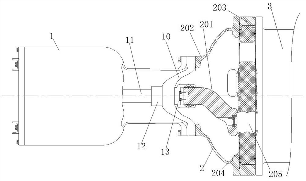
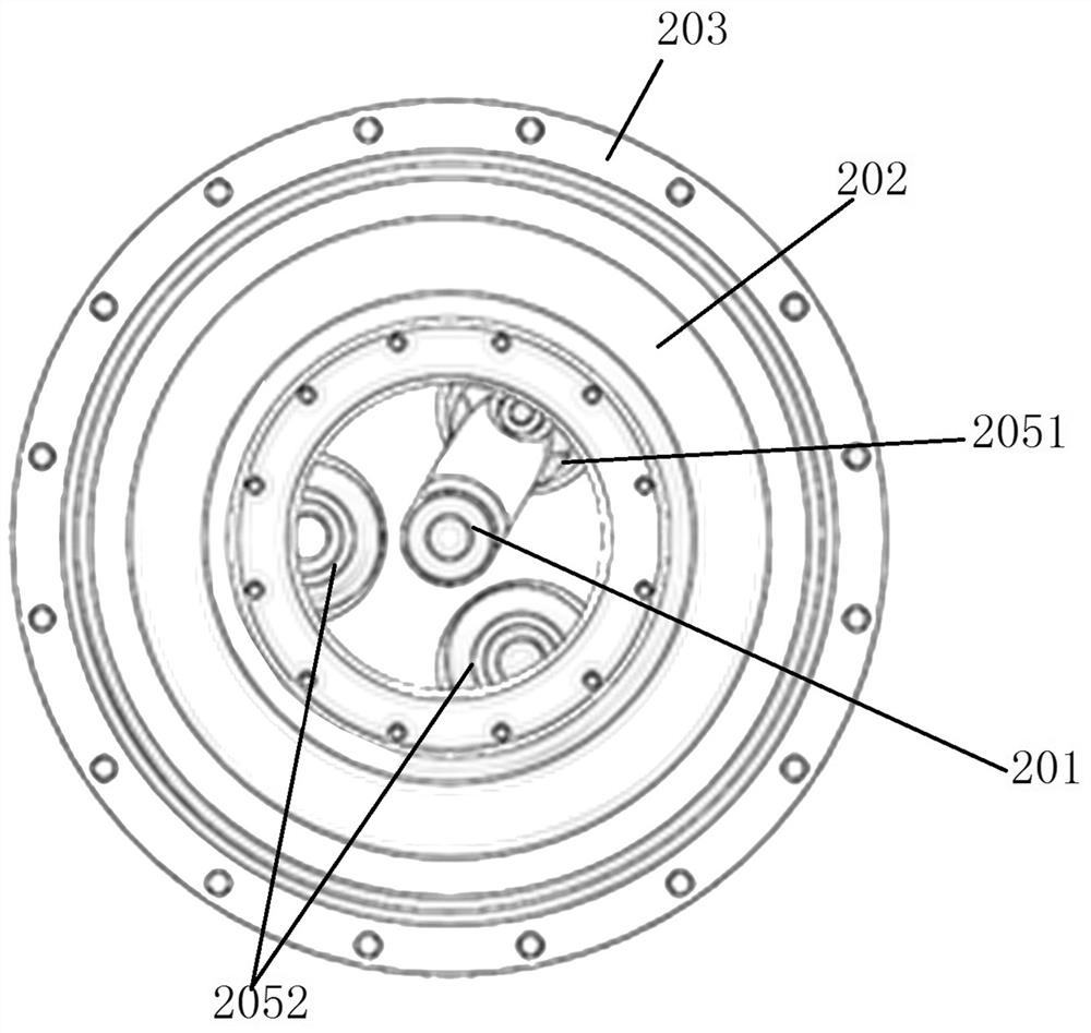
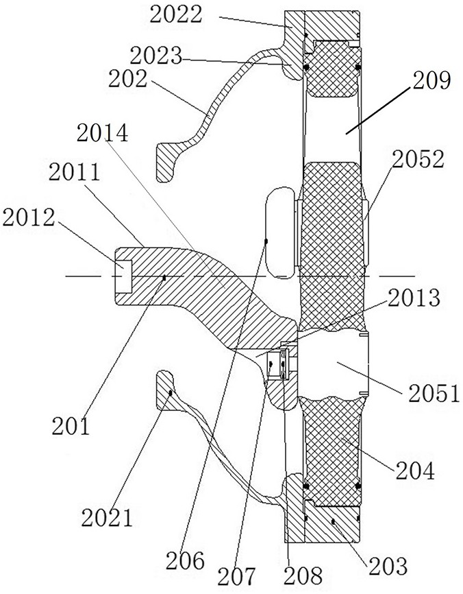
[0066] In this embodiment, the horizontal front end of the three-phase common tank cylinder 3 of GIS is fixedly equipped with a voltage transformer through the transition bus 2, and the three-phase common tank cylinder 3 and the voltage transformer are arranged horizontally, corresponding to the The three-phase conductors arranged in a zigzag shape make use of the obliquely arranged connecting conductors 201 in the transition busbar 2 to ensure that the voltage transformer is centered and fixedly installed on the front end of the three-phase common box cylinder 3, which not only has a beautiful appearance, but also facilitates the assembly of internal parts of the GIS spacing. Moreover, the connecting conductor 201 can choose one phase conductor to realize the power-taking operation, there is no redundant requirement for the three-phase conductors, and the same conductor structure can be used, which can effectively reduce the number of parts, reduce the cost of conductor materi...

specific Embodiment 2

[0082] The main difference from Embodiment 1 is that in Embodiment 1, the rear end of the connecting conductor is detachably and fixedly connected to the corresponding connecting insert. In this exemplary embodiment, it is also possible to directly solder the connecting conductor to the connecting insert.

specific Embodiment 3

[0084] The main difference between it and Embodiment 1 is that in Embodiment 1, anti-loosening washers are provided in the connecting conductors to improve the fastening effect of the fastening screws. In this embodiment, the anti-loosening gasket can also be omitted, and the fixed assembly of the connecting conductor and the connecting insert can be realized only by fastening screws.


PUM


Abstract

The invention relates to a GIS transition bus and a GIS, the transition bus comprises a transition connection shell, a support insulator and a connection conductor, the transition connection shell is used to conveniently realize fixed assembly of a three-phase common box cylinder and a single-phase voltage transformer, the transition connection shell has a smooth reducing section, the radial size of the front end of the transition connection shell is smaller than that of the rear end; and the connection conductor is provided with an inclined extension section, so that a conductive plugging terminal is arranged corresponding to the center of the transition connection shell. According to the transition bus for the GIS, fixed assembly of the three-phase common-box cylinder and the single-phase voltage transformer is conveniently achieved through the transition connection shell, the single-phase voltage transformer and any phase of conductor can be conductively connected through the connecting conductor matched with the conductive insert, electricity taking operation is achieved, and through the inclined extension section on the connection conductor, centering arrangement of the single-phase voltage transformer is convenient to achieve, centering outgoing is convenient, and the overall arrangement coordination of GIS parts is improved.

Description

technical field [0001] The invention belongs to the field of gas insulated switchgear, and in particular relates to a transition bus for GIS and the GIS. Background technique [0002] At present, the isolating switches used by 126kV GIS of domestic and foreign manufacturers are basically three-phase common tanks, and the single-phase PTs and arresters are arranged upwards. The PTs and arresters are generally connected to the isolating switch through a transition welding shell. In practical engineering applications, in order to reduce the overall height of GIS, it is considered to arrange the voltage transformer in the horizontal direction of the disconnector, such as the three-phase common box type gas-insulated metal-enclosed switchgear disclosed in the Chinese utility model patent with the authorized announcement number CN201667503U , which is connected to a voltage transformer at the horizontal side port of the isolating switch through a pot insulator, and the voltage tra...

Claims


Application Information

Patent Timeline
Patent Type & Authority Applications(China)
IPC IPC(8): H02B13/035H02B1/20
CPCH02B13/0356H02B13/0358H02B1/20
Inventor 毕海波黄坤鹏李健康留涛李建彬李鹏赵营吴运泽娄晓丹王清华李伟强刘永超董清华冷龙茂
Owner HENAN PINGGAO ELECTRIC
Why Eureka
Try Eureka