Heat dissipation device for directly pressing power components by utilizing shell

A technology of power components and heat sinks, applied in the field of heat sinks of power components, can solve the problems affecting the service life of power heating components and controllers in controllers, low heat transfer efficiency of power heating components, and large temperature difference of metal heat sinks on heat dissipation surfaces. and other problems to achieve the effect of changing the installation method, fully conducting heat and heat dissipation, and improving the heat dissipation efficiency

Inactive Publication Date: 2016-12-14
NANJING LISHUI ELECTRONICS RES INSITITUE CO LTD
View PDF7 Cites 0 Cited by
  • Summary
  • Abstract
  • Description
  • Claims
  • Application Information

AI Technical Summary

Problems solved by technology

As the power level of the controller increases, the number of power heating elements will also increase, and the labor cost in product production will also increase accordingly. The higher the production volume, the more prominent the contradiction
[0003] In the traditional installation method of power heating elements, the heat dissipation surface contact of the power heating element is only one-sided contact, and the heat conduction can only be dissipated through the shell directly contacting the power heating element, and the waterproof gasket in the shell affects the heat. Conduction factors exist, and the heat transfer efficiency of power heating elements is not high
[0004] Moreover, in the traditional screw installation method, the temperature difference between the heat dissipation surface and the metal heat sink will be relatively large, especially the instantaneous temperature difference, which will affect the controller's ability to withstand heat shocks under heavy loads to a certain extent. , thus affecting the service life of the power heating elements in the controller and the controller

Method used


Image

  • Heat dissipation device for directly pressing power components by utilizing shell
  • Heat dissipation device for directly pressing power components by utilizing shell
  • Heat dissipation device for directly pressing power components by utilizing shell

Examples


Embodiment Construction

[0011] The technical solutions of the present invention will be further described below in conjunction with the accompanying drawings and embodiments.

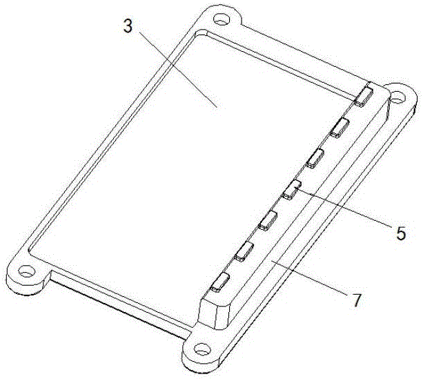
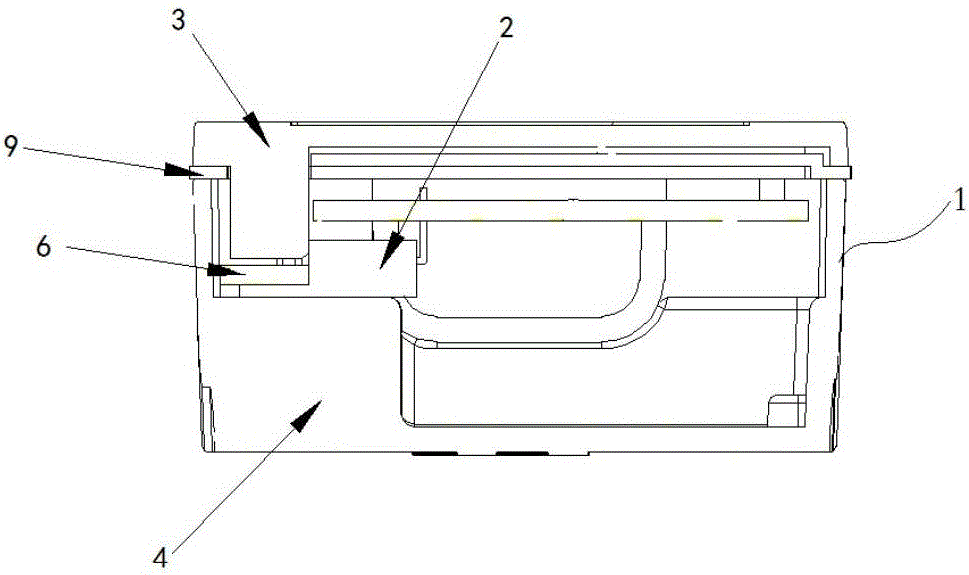
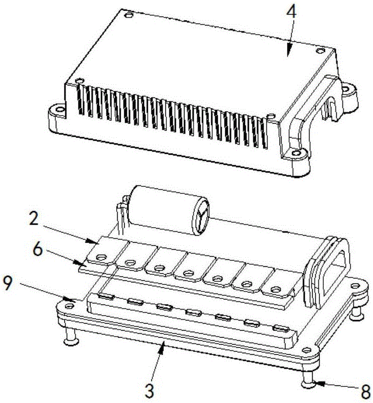
[0012] Such as figure 1 with 2 As shown, the heat dissipation device of the present invention, which utilizes the shell to directly press the power element, includes a shell 1 and several power elements 2, and the shell is made of die-cast aluminum. The casing 1 is composed of an upper casing 3 and a lower casing 4 , and several protrusions 5 are arranged on the upper casing 3 or the lower casing 4 . The following description will be made by taking the example of disposing the protrusion 5 on the upper casing 3 .

[0013] A plurality of protrusions 5 are designed on the upper case 3 corresponding to the positions where the power components 2 are assembled, or steps 7 are provided on the upper case 3 at positions corresponding to the power components 2 to be assembled, and then several protrusions 5 are provided on the steps ...


PUM


Abstract

The invention discloses a heat dissipation device for directly pressing power components by utilizing a shell. The heat dissipation device comprises a shell and a plurality of power components; the shell comprises an upper shell and a lower shell; the upper shell and the lower shell are fixedly assembled together; a plurality of bumps are arranged on the inner wall of the upper shell or the lower shell; the power components are installed in the shell; one surfaces of the power components resist the bumps on the upper shell or the lower shell; the other surfaces of the power components directly resist the inner wall of the upper shell or the lower shell; or, a step is arranged on the upper shell or the lower shell; and a plurality of bumps are arranged on the step.

Description

technical field [0001] The invention relates to a heat dissipation device of a power element, in particular to a heat dissipation device using a shell to directly press and bond the power element. Background technique [0002] Electric bicycle controllers generally have more than 6 power heating elements due to power requirements. From the perspective of its installation method, the traditional method is to install each power heating element on the corresponding metal heat dissipation block with screws to realize heat dissipation. As the power level of the controller increases, the number of power heating elements will also increase, and the labor cost in product production will also increase accordingly. The higher the production volume, the more prominent the contradiction. [0003] In the traditional installation method of power heating elements, the heat dissipation surface contact of the power heating element is only one-sided contact, and the heat conduction can only ...

Claims


Application Information

Patent Timeline
Patent Type & Authority Applications(China)
IPC IPC(8): H05K7/20H05K5/04H05K5/06
CPCH05K7/20436H05K5/04H05K5/061H05K7/20472
Inventor 邓世刚
Owner NANJING LISHUI ELECTRONICS RES INSITITUE CO LTD
Why Eureka
Try Eureka