
Labor-saving brake handle device

A handlebar and labor-saving technology, which is applied to bicycle accessories, bicycle brakes, etc., can solve the problems of unbalanced action points at the grip, easy to pinch hands, and limited adjustment range, etc., and achieve obvious labor-saving effects

Active Publication Date: 2014-10-01
NINGBO TOPRIGHT LEISURE PROD CO LTD
View PDF4 Cites 2 Cited by
  • Summary
  • Abstract
  • Description
  • Claims
  • Application Information

AI Technical Summary

Problems solved by technology

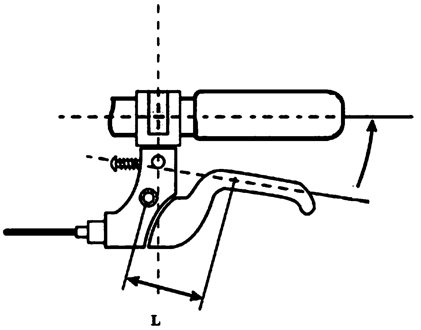
But the problem is that the action point of the grip of the brake handle of the prior art is unbalanced (as figure 1 shown), the closer to the center of the brake shaft, the smaller the moment arm L, and the greater the grip force required to produce the same braking torque
Children's bicycles of the prior art are usually provided with screws for adjustment to adapt to the size of different children's hands, but the problem is that the range of this adjustment is limited, one end of the adjustment screw is exposed, and when braking, the brake handle and the fixing seat There is an open angle between them, which is easy to pinch hands and poses a safety hazard
Especially the brake handles of children's bicycles in the prior art are basically reduced versions of the brake handles of adult bicycles. For children with smaller hands, it is usually difficult to hold the existing brake handles of children's bicycles tightly.
And its grip strength is basically close to the grip strength of adult car brakes. Children's grip strength is relatively small, and their movement ability is limited. It is difficult to achieve the braking effect of timely braking, and there are certain safety hazards

Method used


Image

  • Labor-saving brake handle device
  • Labor-saving brake handle device
  • Labor-saving brake handle device

Examples


Embodiment Construction

[0016] Embodiments of the present invention will be further described below in conjunction with the accompanying drawings.

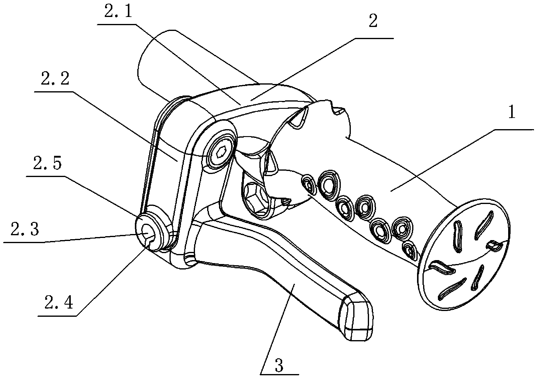
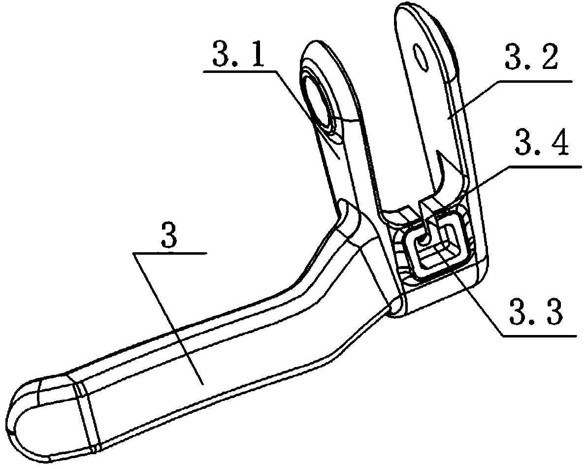
[0017] Such as Figure 1-4 As shown, a labor-saving brake handle device includes a handle 1 and a brake handle 3, and it also includes a connecting piece 2. The connecting piece 2 is composed of a first connecting piece 2.1 and a second connecting piece 2.2. One end of a connecting piece 2.1 is fit and installed on the handle 1, and the other end of the first connecting piece 2.1 is bent downward at a certain angle to form a second connecting piece 2.2, and the brake handle 3 At least one vertical support plate is provided at one end of the support plate, and the end of the support plate is hinged at the junction of the first connecting piece 2.1 and the second connecting piece 2.2, and the second connecting piece 2.1 The lower end and one end of the brake handle 3 are all provided with installation parts for cooperating with the brake line device.

[...


PUM


Abstract

The invention discloses a labor-saving brake handle device. The labor-saving brake handle device comprises a gripping handle (1), a brake handle (3) and a connecting piece (2), the connecting piece (2) is composed of a first connecting piece (2.1) and a second connecting piece (2.2), one end of the first connecting piece (2.2) sleeves the gripping handle (1), the other end of the first connecting piece (2.2) is bent downward by a certain angle to form the second connecting piece (2.2), at least one vertical support plate is arranged at one end of the brake handle (3), the end of the support plate is hinged to the joint of the first connecting piece (2.1) and the second connecting piece (2.2), and a mounting part matched with a brake cable device is arranged at each of the lower end of the bent piece (2.1) and one end of the brake handle (3). The labor-saving brake handle device is compact in structure, uniform in brake handle gripping force, safe, reliable and more labor saving.

Description

technical field [0001] The invention relates to the field of transportation tools such as bicycles and children's bicycles, in particular to a labor-saving brake handle device. Background technique [0002] The brake handle is an important part used to reduce the speed of a bicycle, so as to cope with changes in road conditions or the distance from the vehicle when riding a bicycle. It mainly uses the principle of friction to produce a deceleration effect. When the rider presses the brake handle, the brake lines can be driven sequentially to make the brake clamp arm move, and the brake pads of the brake clamp arm rub against the steel ring to reduce the speed of the vehicle. But the problem is that the action point of the grip of the brake handle of the prior art is unbalanced (as figure 1 As shown), the closer to the center of the brake shaft, the smaller the moment arm L is, and the greater the grip strength of the hand is required to generate the same braking torque. Ch...

Claims


Application Information

Patent Timeline
Patent Type & Authority Applications(China)
IPC IPC(8): B62L3/02
Inventor 张雷方尹伟
Owner NINGBO TOPRIGHT LEISURE PROD CO LTD
Learn More