
Improved structure of brake apparatus of electric vehicle

A braking device and electric vehicle technology, applied in the direction of bicycle brakes, bicycle accessories, etc., can solve problems such as difficult to quickly achieve the braking effect

Inactive Publication Date: 2013-12-18
祝珍海
View PDF8 Cites 2 Cited by
  • Summary
  • Abstract
  • Description
  • Claims
  • Application Information

AI Technical Summary

Problems solved by technology

The safety problem of electric vehicles mainly lies in the braking system of electric vehicles. Most of the electric vehicles on the market today basically adopt measures to brake the front and rear wheels separately, mainly through the brake handle on the handlebar, but this This kind of braking method is often difficult to quickly achieve the braking effect when the vehicle speed is fast, and generally when the speed is fast, people will subconsciously put their feet down to touch the ground to increase the friction effect for braking. In fact, this is a It is a very dangerous action, so how to add a braking device instead of directly touching the ground with both feet to achieve the braking effect is what many people hope to achieve. This will not only achieve the braking effect, but also reduce driving safety hazards

Method used


Image

  • Improved structure of brake apparatus of electric vehicle
  • Improved structure of brake apparatus of electric vehicle
  • Improved structure of brake apparatus of electric vehicle

Examples


Embodiment Construction

[0021] The specific embodiment of the present invention will be further described below in conjunction with accompanying drawing:

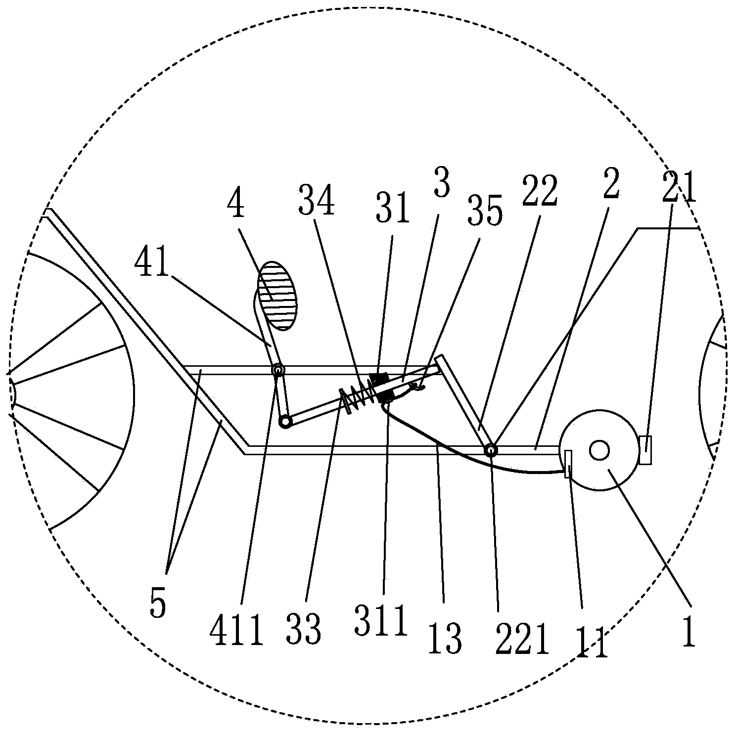
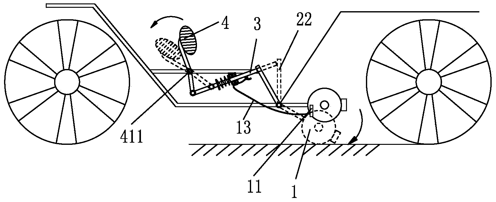
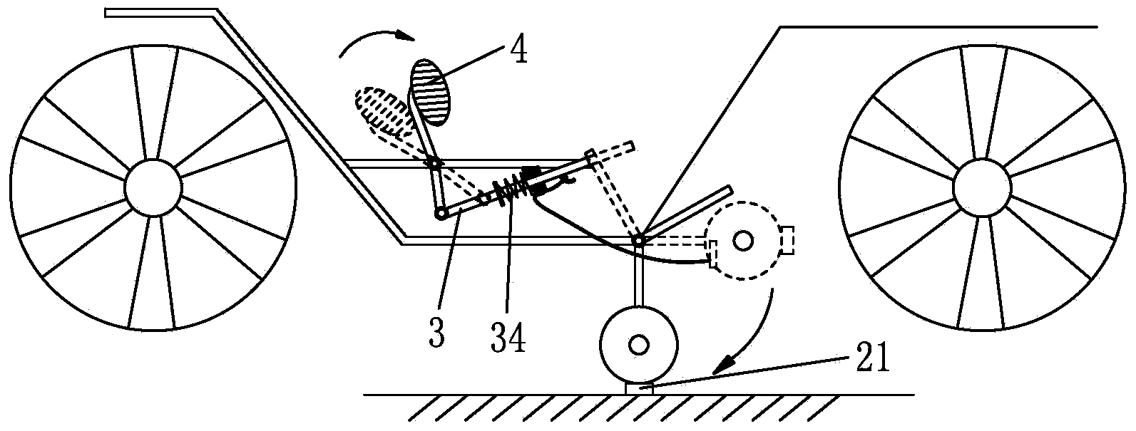
[0022] Such as figure 1 Shown is the schematic diagram of Embodiment 1. In this example, the brake transmission mechanism adopts a link-type transmission. Generally, electric vehicles are hinged with electric vehicle support feet 2 at the bottom of the frame, which are used to support the electric vehicle so that it will not move when parking. , the brake device is provided with a brake wheel 1 on the electric vehicle support foot 2, the brake wheel is set at the bottom of the electric vehicle support foot 2, but not the bottom, the bottom is still used to support the support of the electric vehicle Foot pad 21 is provided with brake caliper 11 on the brake wheel, and the brake caliper is a more general brake for electric vehicles and bicycles. It can be located on both sides of the wheel, and its top is connected to the brake line. , the brake c...


PUM


Abstract

The invention discloses an improved structure of a brake apparatus of an electric vehicle. The improved structure comprises a vehicle frame and a support leg of the electric vehicle. The support leg of the electric vehicle is hinged onto the vehicle frame, a brake wheel is hinged onto the support leg of the electric vehicle, brake calipers which can clamp the brake wheel are arranged on the support leg of the electric vehicle, a brake pedal is arranged at a footrest position of the vehicle frame, a pedal connecting rod is connected to the lower end of the brake pedal, and a transmission mechanism is arranged between the pedal connecting rod and the brake wheel. The improved structure has the advantages that the pedal connecting rod drives the support leg of the electric vehicle via the transmission mechanism, so that the support leg of the electric vehicle can downwardly swing until the brake wheel is landed, at the moment, the transmission mechanism continues applying tensile force to the brake calipers, the calipers clamp the brake wheel, and the purpose of braking the electric vehicle is achieved; a foot braking mode is added for a driver owing to the structure, the problem that the driver needs to step on the ground to brake the electric vehicle at ordinary times is solved, and potential safety hazards are reduced.

Description

technical field [0001] The invention relates to a braking device for an electric vehicle. Background technique [0002] At present, electric vehicles are becoming more and more important in people's lives, mainly because electric vehicles are convenient and flexible for short-distance travel, but the safety of electric vehicles has always been a concern for people. The safety problem of electric vehicles mainly lies in the braking system of electric vehicles. Most of the electric vehicles on the market today basically adopt measures to brake the front and rear wheels separately, mainly through the brake handle on the handlebar, but this This kind of braking method is often difficult to quickly achieve the braking effect when the vehicle speed is fast, and generally when the speed is fast, people will subconsciously put their feet down to touch the ground to increase the friction effect for braking. In fact, this is a It is a very dangerous action, so how to add a braking de...

Claims


Application Information

Patent Timeline
Patent Type & Authority Applications(China)
IPC IPC(8): B62L3/04B62L1/00
Inventor 祝珍海
Owner 祝珍海
Learn More