Hydraulic disk type brake

一种制动器、油压的技术,应用在制动器、制动器类型、轴向上制动器等方向,能够解决车辆旋摆、无法相对运动、车辆轮胎死锁等问题

Inactive Publication Date: 2008-01-30
黄潭城
View PDF4 Cites 2 Cited by
  • Summary
  • Abstract
  • Description
  • Claims
  • Application Information

AI Technical Summary

Problems solved by technology

[0003] Since the rider exerts a very large force on the oil pressure clamp during emergency braking, the braking force of the brake disc is usually too large during emergency braking. At this time, the gap between the brake friction plate set and the brake disc It presents a state of complete tightness and deadlock, which can not move relative to each other. Not only will the tires of the vehicle be deadlocked and the tires will stop immediately on the road, but it will also cause the rider to drive and control the vehicle to produce instant yaw when braking at high speed, causing the rider to experience uncontrollable driving. What's more, there will be accidents such as vehicle swing, rider falling or overturning. Therefore, at present, manufacturers and R&D personnel of various automobiles, electric vehicles, bicycles and locomotives are working hard to study a method that can prevent Improved Hydraulic Disc Brake Structure for Tire Deadlock

Method used


Image

  • Hydraulic disk type brake
  • Hydraulic disk type brake
  • Hydraulic disk type brake

Examples


Embodiment Construction

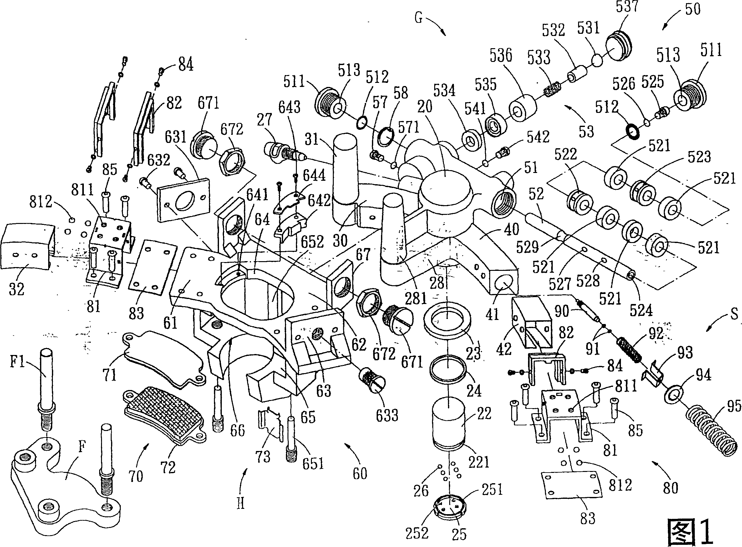
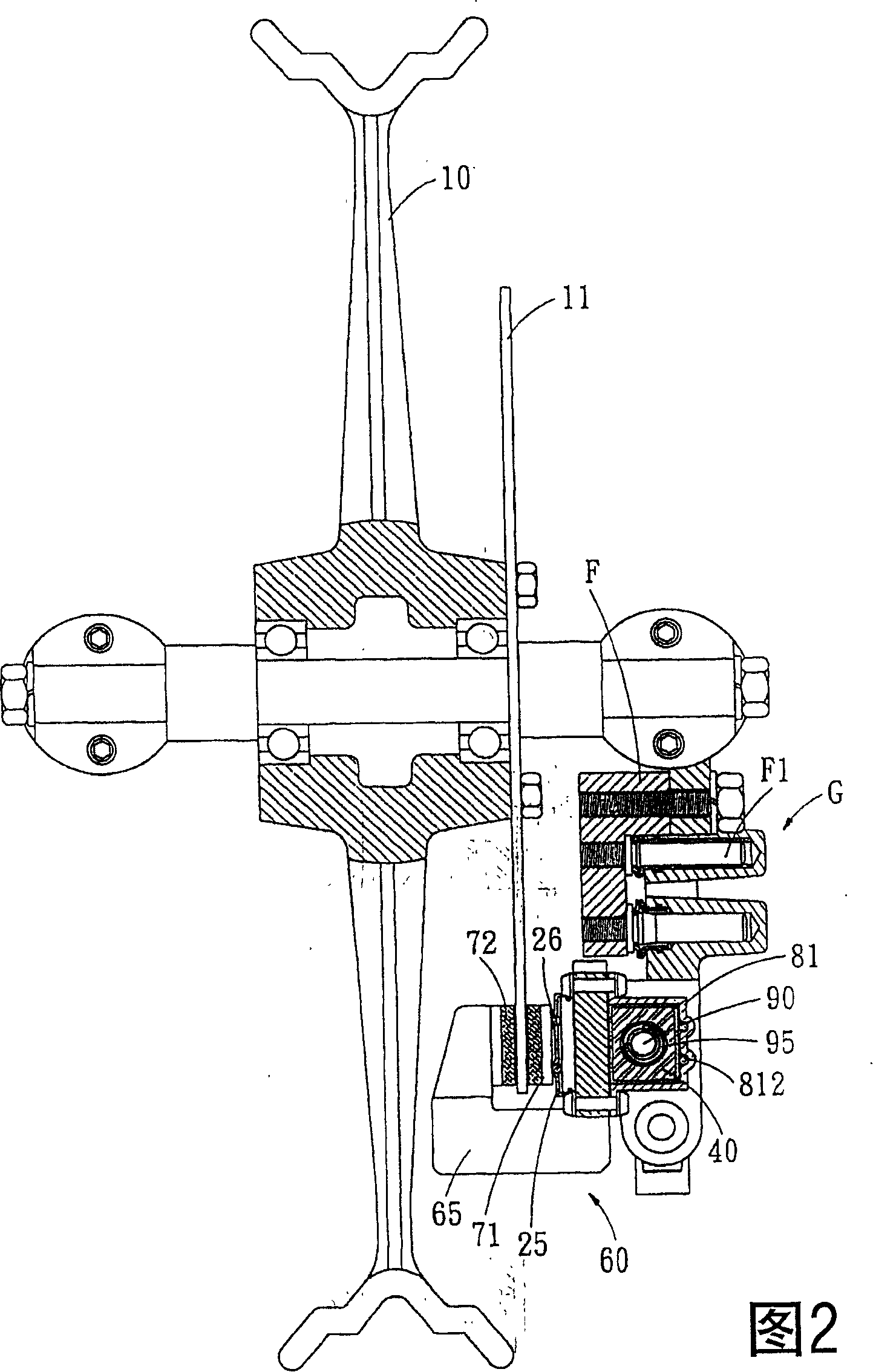
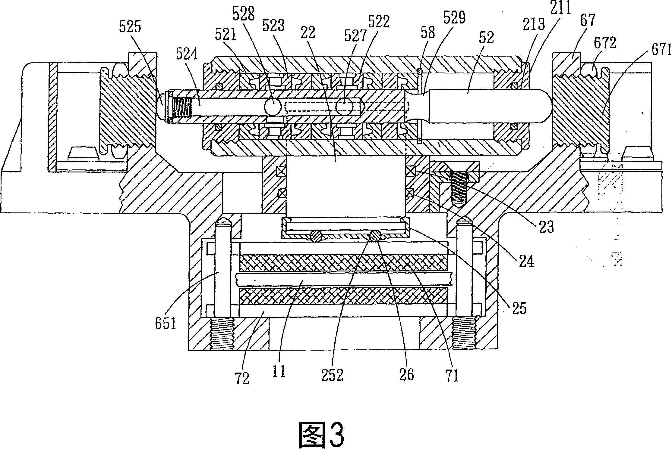
[0112] In order to achieve the above-mentioned purpose, adopted technology, means and other effects, hereby enumerate a preferred embodiment and describe it in detail with the accompanying drawings. It is believed that the purpose, characteristics and other advantages of the creation of this case have a deep and specific understanding; First please refer to Fig. 1, 2, 3, 4, 5, the present invention is assembled on a vehicle wheel frame 10, and corresponds to the brake disc 11 of the vehicle, which includes: a body G, a sliding seat H , a spring set S and a positioning plate F and other main components, and the hydraulic oil W flows through the oil pressure groove and the control valve group in the body G, wherein:

[0113] The positioning plate F is fixedly positioned on the vehicle wheel frame 10 with screw locks, and two protruding positioning studs F1 are mounted on the corresponding side of the positioning plate F with screws.

[0114] The body G is provided with a shell s...


PUM


Abstract

A hydraulic disk brake includes a slide carriage and a body. The slide carriage cooperating with a restoring spring is attached to the body, and the body is provided with a control valve assembly. The body is provided with a groove for transferring oil. The brake disc is braked by a braking assembly by means of increasing the oil pressure in the groove. When braking, the slide carriage moves back and forth on an arc path with respect to the body by means of the control valve assembly, and the brake disc is clamped and released repeatedly, which make it possible for the braking action of the present invention to prevent the hydraulic disc brake of the vehicle from locking the brake disc, and to eliminate the troubles of unsteadily driving and skidding which take place in hard braking.

Description

technical field [0001] The invention relates to a hydraulic disc brake device for a vehicle, in particular to a hydraulic disc brake. Background technique [0002] At present, the common vehicle hydraulic disc brake equipment on the market includes: automobiles, electric vehicles, locomotives, bicycles and other self-propelled vehicles) all use the oil pressure boost of a brake cylinder to force the brakes located on both sides of the brake disc. brake friction plate group, and the two brake friction plates that are forced to move will pinch the brake disc, and the vehicle is stopped to produce a braking effect by the friction force between the two brake friction plates and the brake disc); but the above-mentioned existing structure Still can produce following deficiency and defective practically: [0003] Since the rider exerts a very large force on the oil pressure clamp during emergency braking, the braking force of the brake disc is usually too large during emergency br...

Claims


Application Information

Patent Timeline
Patent Type & Authority Patents(China)
IPC IPC(8): B60T1/06B60T8/00F16D55/226B60T1/00B60T8/32B60T8/52B62L1/00F16D65/14
CPCF16D65/18F16D2055/0016B60T8/52F16D2121/02B60T8/3225B62L1/005B60T8/74F16D55/228
Inventor 黄潭城
Owner 黄潭城
Why Eureka
Try Eureka