Main shaft remaining gap eliminating construction for direct driving rotary distance motor apparatus

A direct-drive, spindle technology, applied in electromechanical devices, control of mechanical energy, electrical components, etc., can solve the problems of increasing the wear and noise of each component, affecting product life, and unable to detach the heavy body for modular application, etc. Achieve the effect of improving product life, eliminating spindle clearance, simplifying assembly work and reliability

Inactive Publication Date: 2009-02-04
HIWIN MIKROSYST
View PDF0 Cites 2 Cited by
  • Summary
  • Abstract
  • Description
  • Claims
  • Application Information

AI Technical Summary

Problems solved by technology

[0004] First, this kind of conventional direct-drive torque motor device must be configured on the machine platform for rotation operation, and the heavy machine body cannot be disassembled for modular application, and the market has been expecting to develop a simple and independent application in various angles. Control, speed control, precision control products;
[0005] Second, if the conventional product is installed on the machine for rotation operation, there is no suitable component to support and tighten the inner rotor 11 and shaft 12 of the direct-drive torque motor, resulting in clearance between the shaft 12 and other components during operation. , this kind of shaft clearance is likely to cause wear and noise between components, which will greatly affect the life of the product
[0006] Third, in addition, after the inner rotor 11 and the shaft member 12 of the direct-drive torque motor have operated for a certain period of time, they are also affected by deformation and wear and gradually change the clearance more and more seriously. This kind of clearance of the shaft member 12 It will increase the wear and noise of each component, and it is the main reason for shortening the life of the product

Method used


Image

  • Main shaft remaining gap eliminating construction for direct driving rotary distance motor apparatus
  • Main shaft remaining gap eliminating construction for direct driving rotary distance motor apparatus
  • Main shaft remaining gap eliminating construction for direct driving rotary distance motor apparatus

Examples


Embodiment Construction

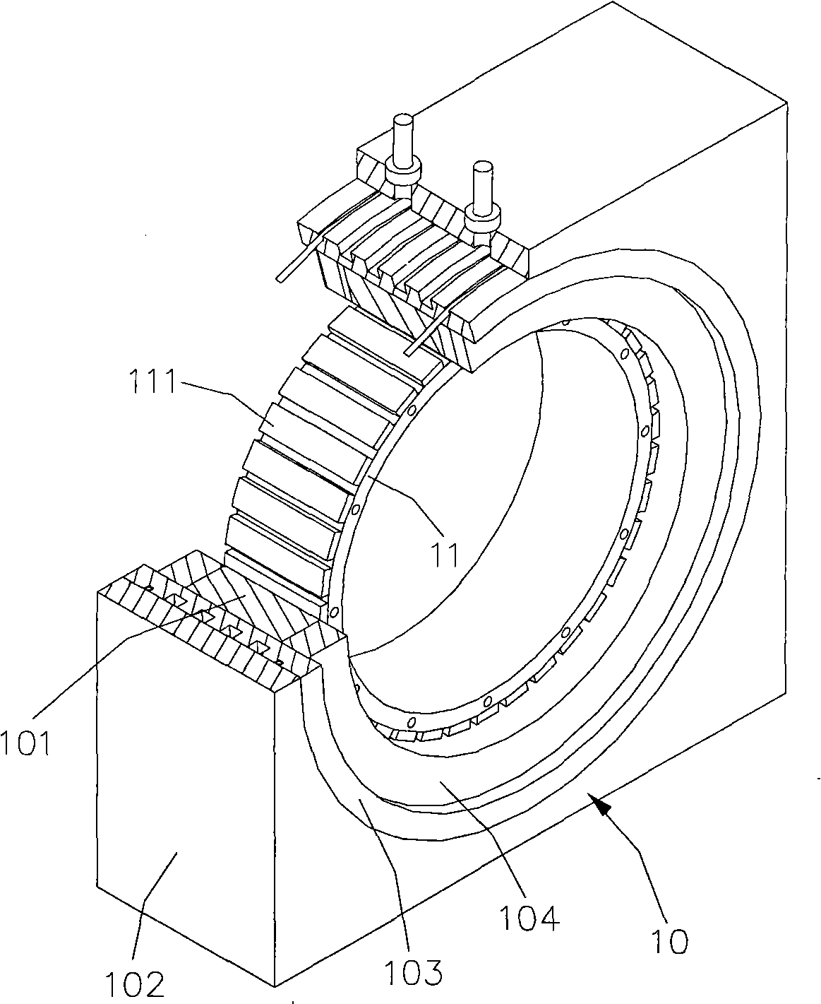
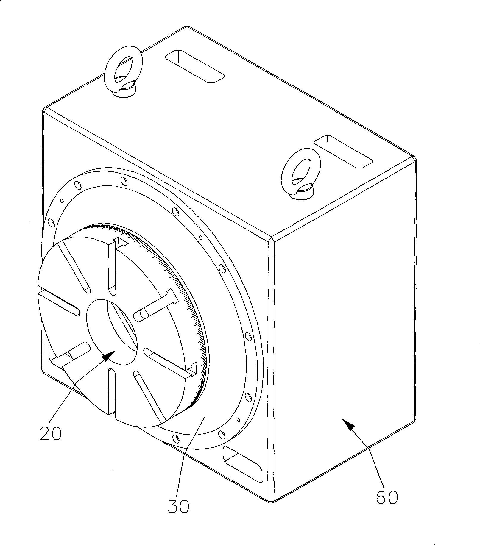
[0021] Please refer to the embodiment of the present invention image 3 , 4 And 5, the main shaft clearance elimination structure of the direct drive torque motor device of the present invention includes a main shaft 20, a braking element 30, a bearing assembly 40, a direct drive torque motor 50, a body 60, and a position detection element 70 And an adjusting nut 80; Its structure description is as follows:

[0022] The outer diameter of the main shaft 20 is gradually tapered from one end to the other end to make the first level 21, the second level 22, the third level 23, the fourth level 24 and an external thread segment 25, and the external thread segment 25 is made on the end of the main shaft 20;

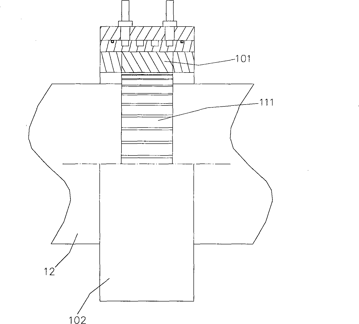
[0023] The braking element 30 has an inner side corresponding to the first level 21 of the main shaft 20 and a positioning portion 31 on the outer side;

[0024] The bearing assembly 40 includes a first oil seal 41, a main bearing 42, a second oil seal 43 and an auxiliary ro...


PUM


Abstract

The invention discloses a spindle clearance eliminating structure of a direct-drive torque motor device, comprising main elements of a body, a direct-drive torque motor, a spindle, a bearing assembly and an adjusting nut; and a plurality of layers of the spindle are utilized to locate the torque motor and the bearing assembly, then the torque motor and the bearing assembly locate the body, an auxiliary roller bearing is arranged in the bearing assembly, and the auxiliary roller bearing butts against the middle part of the body and the spindle, additionally, a screw thread is made on the tail end of the spindle, and the adjusting nut is fed to lock and locate all elements on the spindle. The structure can be applied on assembling direct-drive torque motor devices, and can simplify the assembly work and improve the reliability, as well as eliminating the spindle clearance and improving the product life.

Description

technical field [0001] The invention relates to a main shaft clearance elimination structure, in particular to a main shaft clearance elimination structure of a direct drive torque motor device. Background technique [0002] Today's motor devices are more and more used in industry. The main types of devices are outer rotors, inner rotors, etc. In addition to the high-precision effect of feed transmission, they have low friction loss rate and energy conversion. The advantages of high efficiency and low noise, therefore, the importance of motor devices for various industrial applications today cannot be overstated. [0003] The current direct-drive torque motor device is suitable for driving shaft equipment, such as: automation equipment, indexing tables and various machine tools; please refer to figure 1 , 2 In addition to the main shaft clearance elimination structure of the conventional direct-drive torque motor device, the coil 101 of the stator base 10 is matched with t...

Claims


Application Information

Patent Timeline
Patent Type & Authority Applications(China)
IPC IPC(8): H02K7/00H02K7/08
Inventor 郑复源赵志宪
Owner HIWIN MIKROSYST
Why Eureka
Try Eureka