Fastening assemblies and components thereof

a technology of fastening assemblies and components, applied in the direction of fastening means, fastening tools, sheet joining, etc., can solve the problems of difficult to tell which fastening assemblies the studs belong to, low clearance required to remove a panel, and many existing captive fastening assemblies are also quite delica

Inactive Publication Date: 2005-08-04
PILGRIM SCREW CORP
View PDF58 Cites 12 Cited by
  • Summary
  • Abstract
  • Description
  • Claims
  • Application Information

AI Technical Summary

Benefits of technology

[0008] The present disclosure provides a fastening assembly that includes a “hold-out” feature that allows a stud to be removed or extended from a fastening assembly at several predetermined positions, allowing panels to be removed while retaining the positions of the screws. This is especially desirable when removing curved panels from a curved substructure, for example, when it is desirable to have the studs on the curved portions of the cover removed or extended by a greater amount than those on the flat or planar portion of the cover to provide additional clearance when removing the cover from the substructure. Another feature of the present disclosure is the provision of a fastener with evenly distributed forces along the grommet assembly, rather that localized distribution of force at the tip of a stud. This results in a secure fit of the stud within the grommet assembly and decreases the chance that the stud may be inadvertently released from its captive position.
[0010] In one embodiment, the present disclosure is directed to a fastening assembly that includes a stud that may be positioned in a plurality of predetermined extended positions while being maintained in a captive position within the stud assembly. The fastening assembly includes a grommet assembly for attachment to a cover, which includes a retaining ring having inwardly extending tabs. A plurality of engagement members, which may be lobes or ribs, are disposed within longitudinally extending channels of a stud. The lobes or ribs engage with the tabs of the retaining ring. As the stud is inserted or removed, the tabs slide within the channels of the stud, engaging successive lobes or ribs. Such a structure allows the stud to remain captive in the stud assembly during removal of a cover from a panel, and further allows the stud to have several extended predetermined positions. This is advantageous when the clearance between the panel and the cover is minimal, and it is desirable to remove the stud as far as possible from the stud assembly while maintaining the stud in a captive position.
[0011] In another embodiment, the fastening assembly includes a nut that includes a plurality of flanges. Preferably, the nut is constructed form a material having a memory, such as a shape memory alloy, which allows it to flex or spring back to its original shape after being subjected to a force. The construction and material of the nut allows the force exerted on a stud when it is inserted into a grommet assembly to be distributed substantially evenly along the length of the nut, rather than being localized at one end of the nut.
[0013] In another embodiment, the fastening assembly includes a receptacle that includes a sealed nut unit, which allows the fastening assembly to be used in regions in which there is a pressure differential.

Problems solved by technology

This is problematic when the clearance required to remove a panel is minimal.
In such situations, the studs must be removed from the fastening assembly, which is problematic because it is easy to lose, drop and confuse the studs, and thereafter it is difficult to tell which fasteners the studs belong to when reattaching the panel to the substructure.
Many existing captive fastening assemblies are also quite delicate and are unable to withstand the force associated with the use of pneumatic drills, which increases the amount of time required to remove and re-install panels.
Some fastening assemblies have reduced life due to breakage of retaining rings, as well as other components of the assemblies.
When the retaining ring breaks, depending on the design of the fastener, it often may result in the screw or stud falling out of the assembly, defeating the purpose of using a “captive” fastener assembly.
Another common type of failure is due to “foreign object debris” (FOD), which is common in fastening assemblies that include a hole in the stud or screw which becomes filled with debris over time.
This results in a secure fit of the stud within the grommet assembly and decreases the chance that the stud may be inadvertently released from its captive position.

Method used


Image

  • Fastening assemblies and components thereof
  • Fastening assemblies and components thereof
  • Fastening assemblies and components thereof

Examples


Embodiment Construction

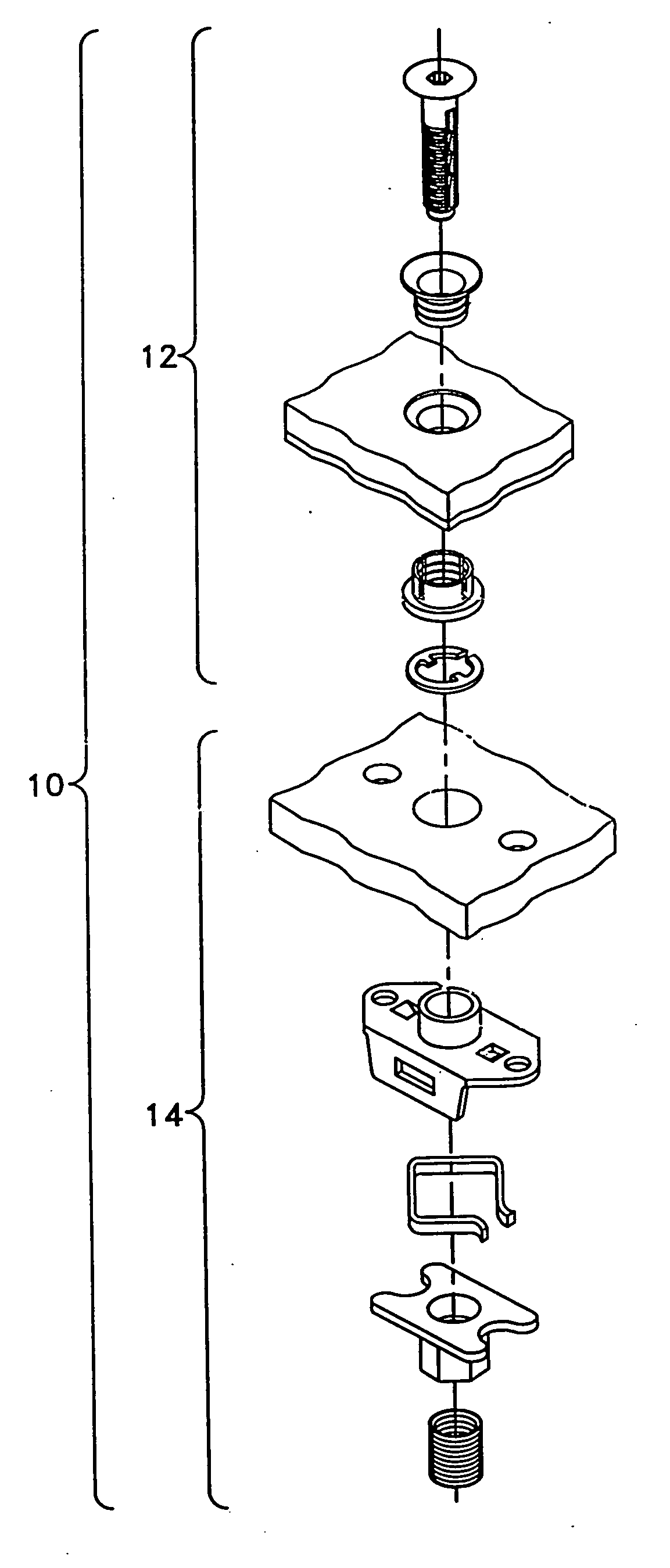
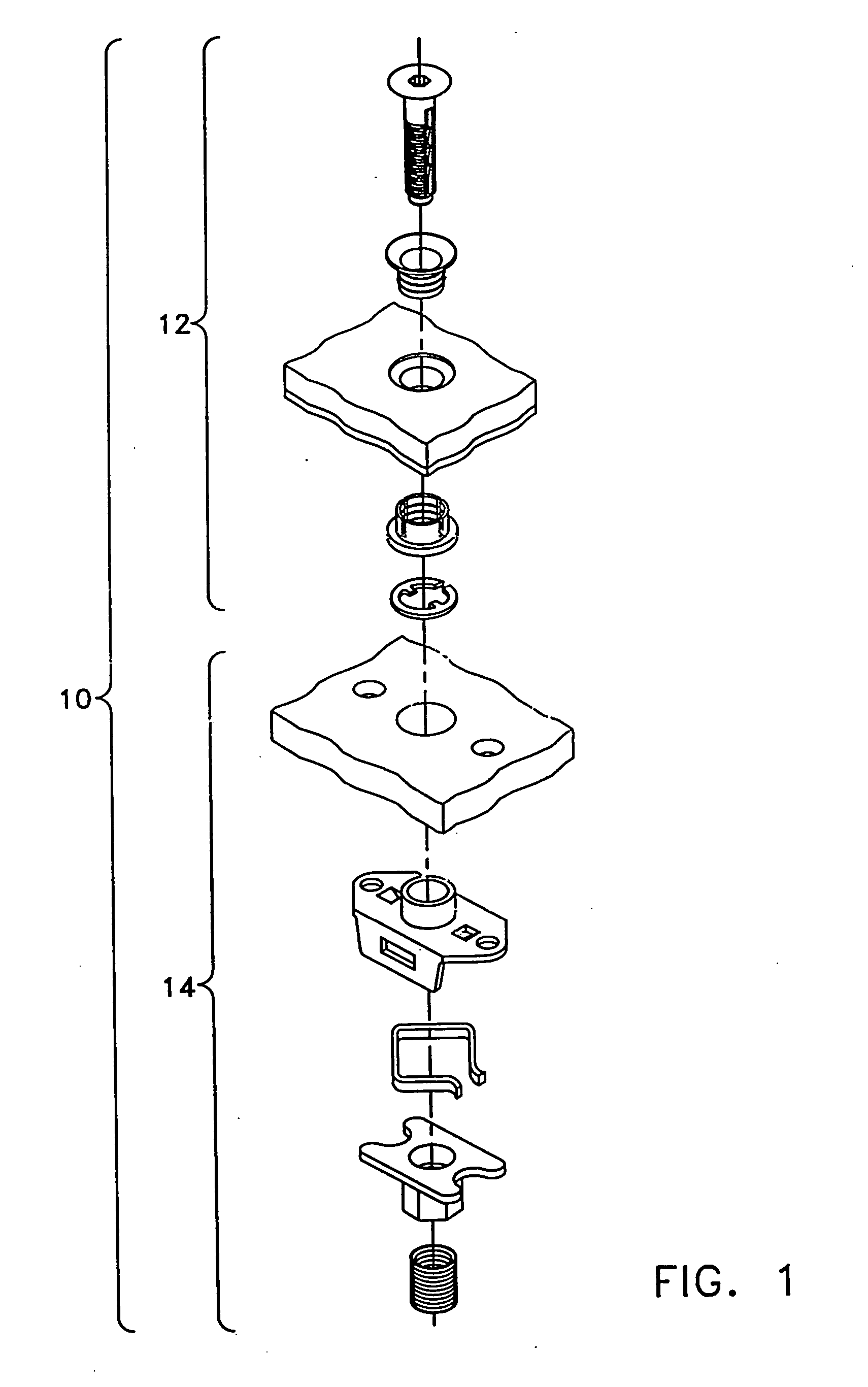
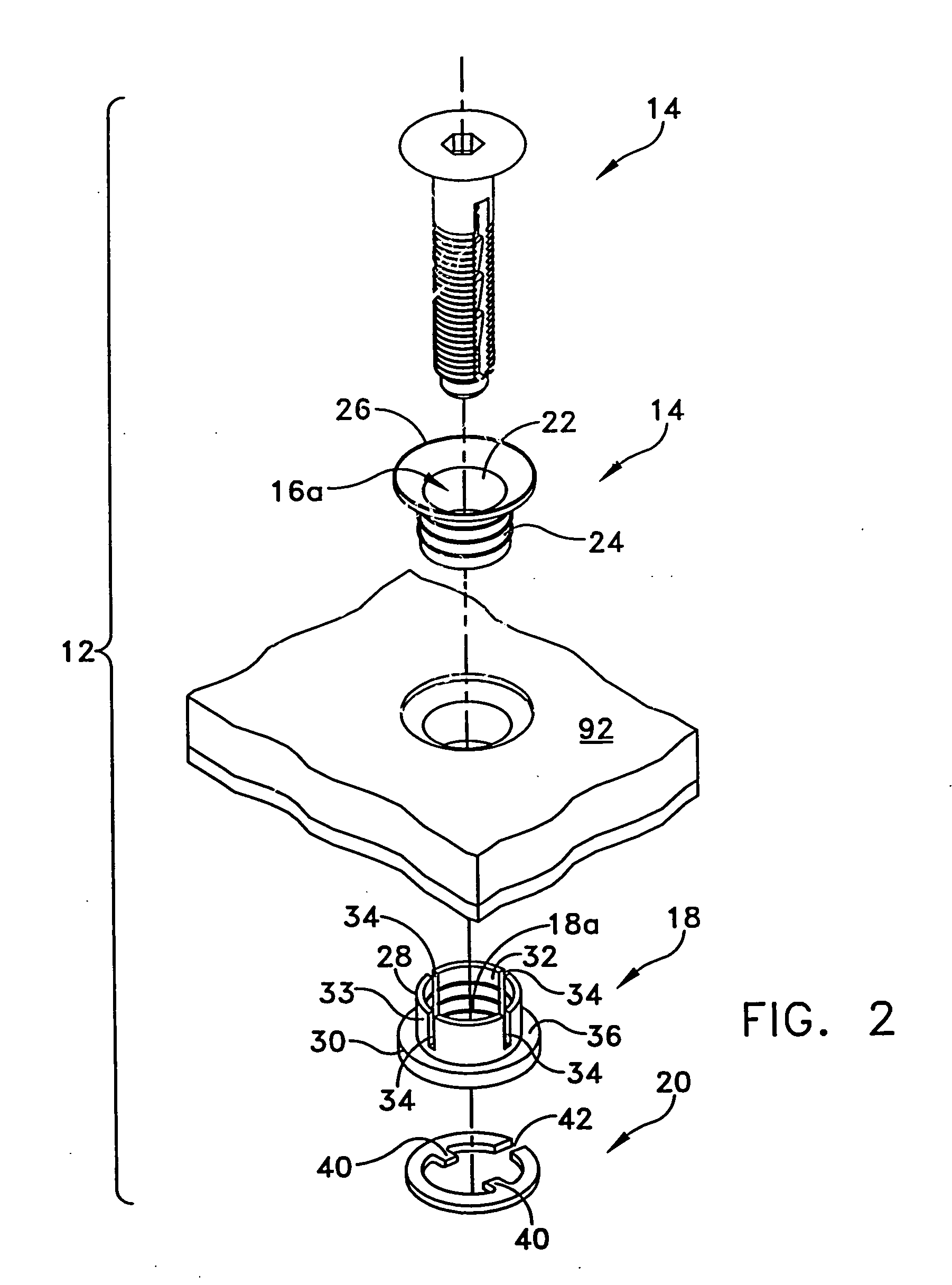
[0072] The present disclosure is directed to a fastening assembly that may be used in high stress environments for attaching a cover to a panel, such as covers used to close access openings in panels of an aircraft. In some embodiments, the present fastening assemblies may include stud assemblies that allow the stud to be positioned in several predetermined extended positions while remaining captive within the stud assembly. Such a feature is useful, for example, when curved covers are attached to curved panels using a plurality of fastening assemblies, each of which may require different stud clearances in order to remove the cover from the panel. In some embodiments, the fastening assembly may include a nut that provides even distribution of stress along the nut. In other embodiments, the fastening assembly may be configured and dimensioned to be attached to a panel using a single bolt or rivet, which allows the fastening assembly to be used in otherwise inaccessible regions. In o...


PUM


Abstract

A fastening assembly is provided. The fastening assembly includes provision for a stud to be positioned in a plurality of predetermined extended positions, minimizing the amount of clearance required for removing a cover from a substructure.

Description

RELATED CASES[0001] Priority is hereby claimed under 35 U.S.C. § 119(e) to commonly owned and co-pending U.S. Provisional Patent Application No. 60 / 288,253, filed on May 2, 2001; to commonly owned and co-pending U.S. Provisional Patent Application No. 60 / 338,930, filed on Dec. 6, 2001; and to commonly owned and co-pending U.S. Provisional Patent Application No. 60 / 352,059, filed on Jan. 24, 2002, each of which is incorporated herein by reference in its entirety.BACKGROUND [0002] 1. Technical Field [0003] This disclosure relates generally to a fastening assembly and components of the fastening assembly and, more particularly, to a structural fastener assembly and components of such a fastening assembly, which may be for attaching a cover or panel to a substructure, particularly in high stress environments. [0004] 2. Related Art [0005] A variety of fastener assemblies are known for attaching a panel to a substructure, for example, such as attaching a panel to an aircraft structure. Su...

Claims


Application Information

Patent Timeline
Patent Type & Authority Applications(United States)
IPC IPC(8): B64C1/12F16B5/02F16B21/18
CPCB64C1/12Y10S411/999F16B21/186F16B5/0208
Inventor ATTANASIO, GERARD E.
Owner PILGRIM SCREW CORP
Why Eureka
Try Eureka