Intake control device for internal combustion engine

a control device and internal combustion engine technology, applied in engine controllers, machines/engines, valve arrangements, etc., can solve the problems of increased intake air leakage, increased idling speed, and increased air tightness of throttle valves, so as to enhance rigidity and strength of the housing connecting ribs

Inactive Publication Date: 2006-10-10
DENSO CORP
View PDF27 Cites 14 Cited by
  • Summary
  • Abstract
  • Description
  • Claims
  • Application Information

AI Technical Summary

Benefits of technology

[0012]In view of the foregoing problems, it is an object of the present invention to provide an intake control device for an internal combustion engine, the intake control device having a structure, in which deformation arising after forming a throttle body is not apt to exert influence directly against the diameter of a throttle bore of the throttle body, even when the throttle body is integrally formed of resin. Specifically, contraction after forming the throttle body and deformation arising in a flange of the throttle body after mounting the throttle body to the engine via the flange, are not apt to directly exert influence against the diameter of a throttle bore of the throttle body, so that the clearance between the throttle bore and the outer periphery of the throttle valve can be enhanced.
[0013]It is another object of the present invention to provide an intake control device for an engine, the intake control device being capable of restricting an amount of intake air leaking in an idling operation, in which a throttle valve is in a full-closing position. Furthermore, it is another object of the present invention to provide an intake control device, in which a throttle valve is capable of being restricted from causing a failure in operation and is capable of being restricted from causing seizure in movement thereof.
[0015]In this structure, the housing connecting rib, which support the motor housing portion, is directly connected with the flange portion, so that rigidity and strength of the housing connecting rib can be enhanced. Thereby, the housing connecting rib can steadily support the motor housing portion, which accommodates the motor being a component heavier than the throttle body.

Problems solved by technology

As a result, air tightness of the throttle valve 104 in the full-closing position may be degraded, and a leakage amount of intake air increases in the full-closing position in an idling operation.
Accordingly, the idling speed may become larger than a predetermined idling speed, and fuel consumption may increase in the idling operation.
As a result, the throttle opening degree may not conform to the accelerator position, and drivability may be degraded.

Method used


Image

  • Intake control device for internal combustion engine
  • Intake control device for internal combustion engine
  • Intake control device for internal combustion engine

Examples


first embodiment

[First Embodiment]

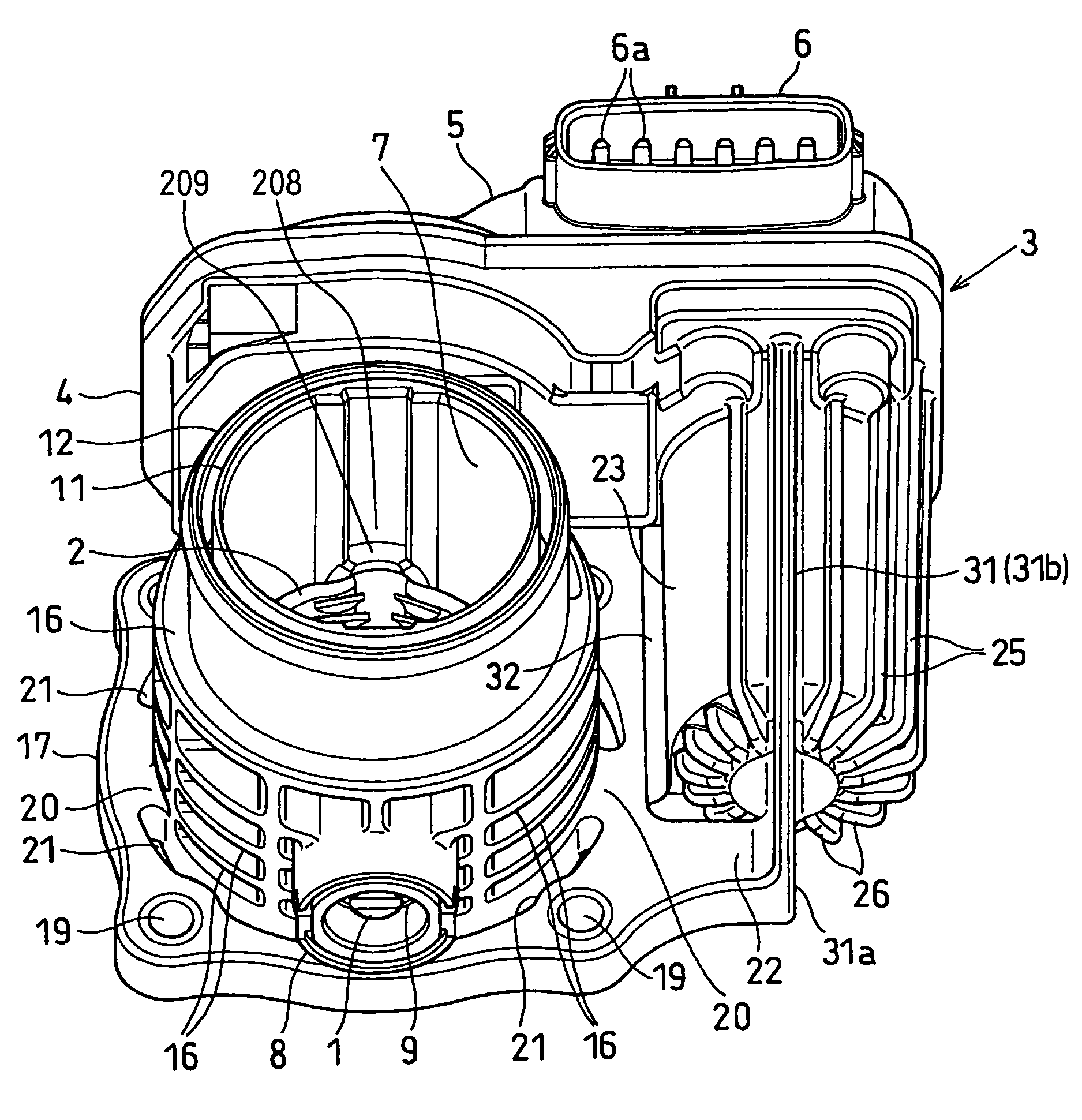
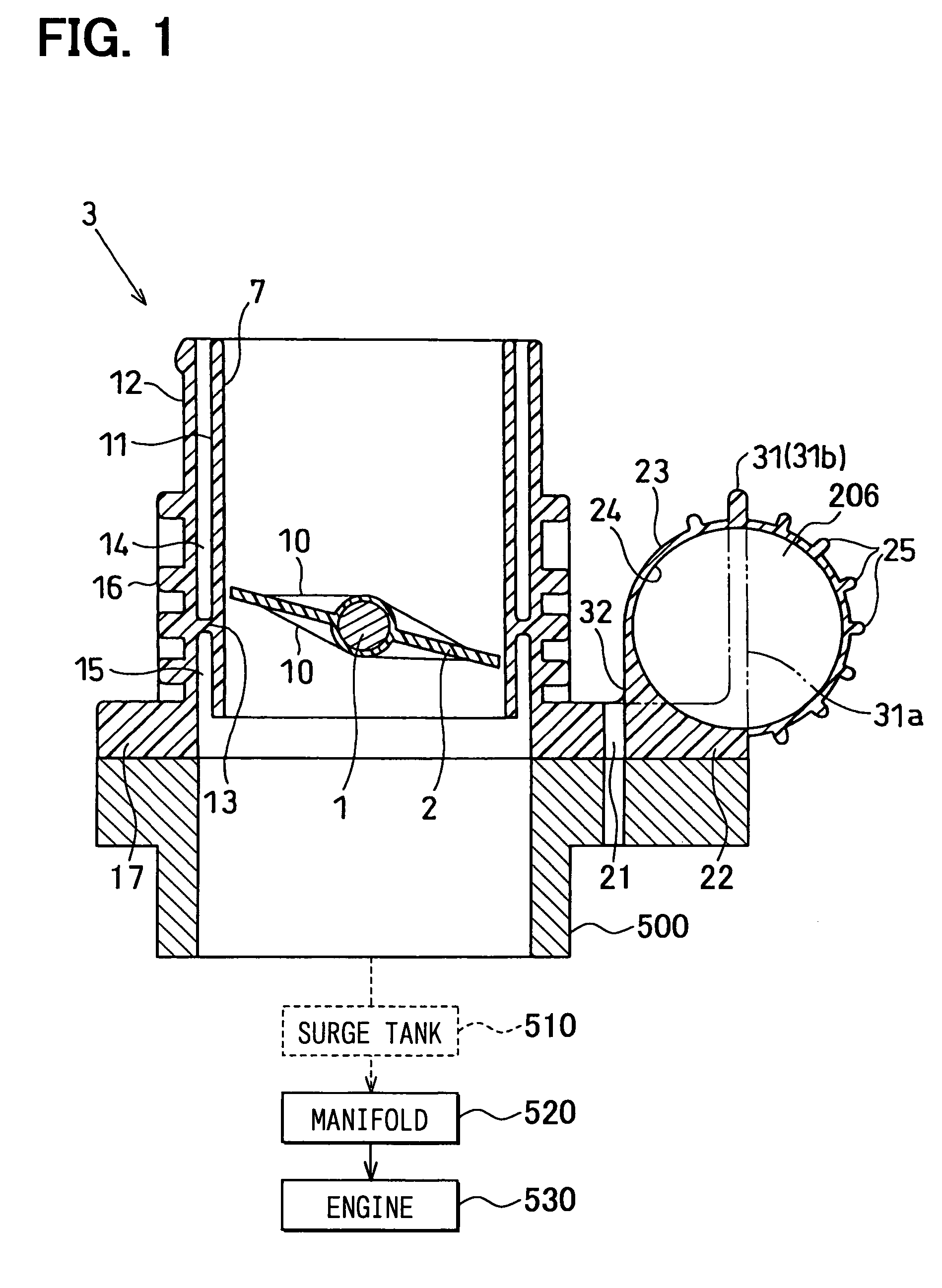
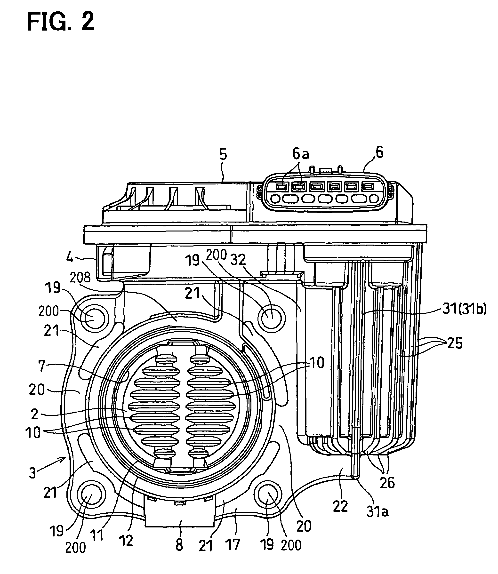
[0025]An intake control device (intake air control device) is provided to a vehicle such as an automobile. The intake control device changes an amount of intake air flowing into respective cylinders (combustion chambers) of an internal combustion engine such as a gasoline engine, in accordance with an accelerator position operated by a driver to control engine rotation speed and engine torque.

[0026]As shown in FIGS. 1 to 4, the intake control device includes a motor 206, a throttle shaft 1, a throttle valve 2, a return spring (not shown), a throttle body 3, and an ECU (engine control unit). The motor 206 is operated in accordance with an accelerator position operated by a driver. The throttle shaft 1 is driven by the motor 206. The throttle valve 2 is a butterfly-type valve rotated together with the throttle shaft 1. The return spring biases the throttle valve 2 to the direction, in which the throttle valve 2 is in a full-closing position. The throttle body 3 rotat...


PUM


Abstract

An intake control device includes a throttle valve and a throttle body. The throttle valve rotates to control intake air. The throttle body includes a cylindrical throttle bore portion defining a circular throttle bore that accommodates the throttle valve. The throttle body includes a cylindrical motor housing portion arranged on the radially outer side of the throttle bore portion. The motor housing portion defines a motor accommodating hole, in which a motor is accommodated to rotate the throttle valve. The throttle body includes a flange portion that extends from one axial end of the throttle bore portion to the radially outer side thereof. The throttle body is connected to the engine via the flange portion. The throttle body is formed of resin integrally with a housing connecting rib that connects the flange portion directly with the motor housing portion.

Description

CROSS REFERENCE TO RELATED APPLICATIONS[0001]This application is based on and incorporates herein by reference Japanese Patent Application No. 2004-198245 filed on Jul. 5, 2004.FIELD OF THE INVENTION[0002]The present invention relates to an intake control device for an internal combustion engine, the intake control device controlling opening degree of a throttle valve, which is rotatably supported by a throttle body, using a motor in accordance with an accelerator position operated by a driver.BACKGROUND OF THE INVENTION[0003]A conventional intake control device for an internal combustion engine controls opening degree of a throttle valve at a predetermined opening degree by operating a motor in accordance with an accelerator position operated by a driver.[0004]The clearance between the surface of a throttle bore of a throttle body and the outer periphery of the throttle valve, when the throttle valve is in a full-closing position, exerts a large influence to a performance in air ti...

Claims


Application Information

Patent Timeline
Patent Type & Authority Patents(United States)
IPC IPC(8): F02D9/08F16K1/22
CPCF02D11/10F02D11/107F02D2011/108
Inventor IWAOKA, SHINTANIMURA, HIROSHISHIMADA, HIROKI
Owner DENSO CORP
Why Eureka
Try Eureka