Vacuum drilling system

a vacuum drilling and vacuum technology, applied in the field of vacuum drilling systems, can solve the problems of reducing the cutting ability of the drill bit, increasing the generation of heat, affecting the drilling process, etc., and achieves the effects of improving heat dissipation and chip removal, and reducing the friction between the drill bit and the bushing

Inactive Publication Date: 2009-07-21
THE BOEING CO
View PDF38 Cites 15 Cited by
  • Summary
  • Abstract
  • Description
  • Claims
  • Application Information

AI Technical Summary

Benefits of technology

[0006]In an exemplary embodiment, the present invention provides an improved vacuum drill bit having a plurality of grooves arranged axially along the outer surface of the drill bit body. The improved drill bit of the present invention can be used in an exemplary drilling system of the present invention in which the drill bit is guided by a bushing, with minimal spacing between the bushing and the drill bit body. The grooves act to minimize the friction between the drill bit and the bushing and provide air flow for improved heat dissipation and chip removal.
[0007]The drill bit of the present invention can also be used advantageously in transfer drilling applications in which a hole in one part can be used to guide the drilling of a hole in a mating part. By minimizing the friction between the drill bit body and the guiding part, the aforementioned grooves allow the clearance between the drill bit body and the guide hole to be minimized, thus maximizing the precision of the hole transfer, while promoting heat dissipation and chip removal.

Problems solved by technology

The drilling of various materials often generates chips which, unless conveyed away from the cutting features of the drill bit, can impede the drilling process.
Without effective removal of the chips thus generated, chip compaction often occurs, reducing the drill's ability to cut, increasing the generation of heat, and reducing the life of the drill.
This, however, leads to greater friction between the drill bit and the guiding means and thus to increased heat generation.
Heat degrades the life of the drill and promotes chip compaction.

Method used


Image

  • Vacuum drilling system
  • Vacuum drilling system
  • Vacuum drilling system

Examples


Embodiment Construction

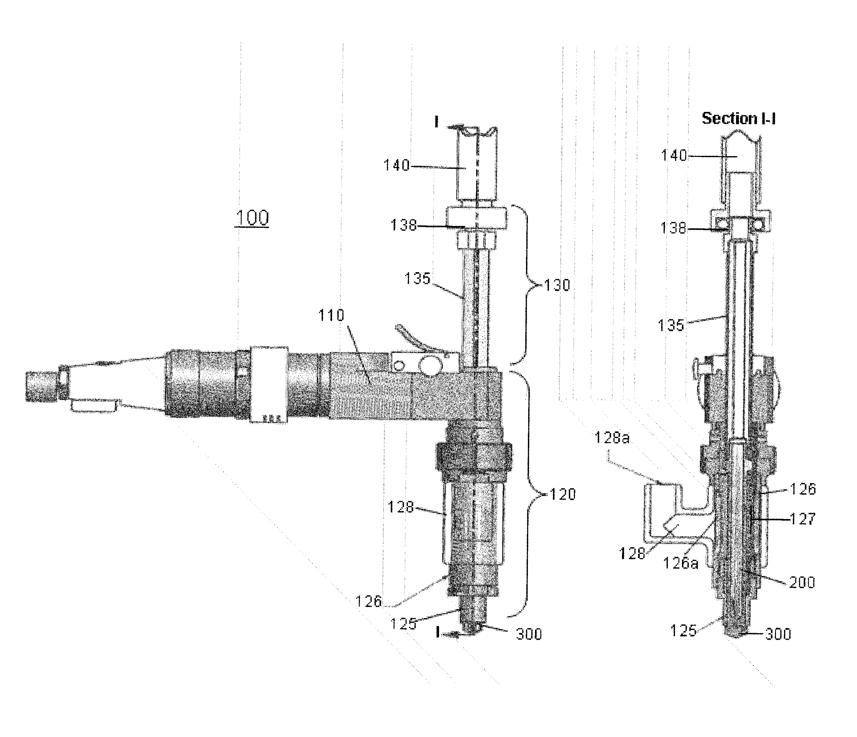
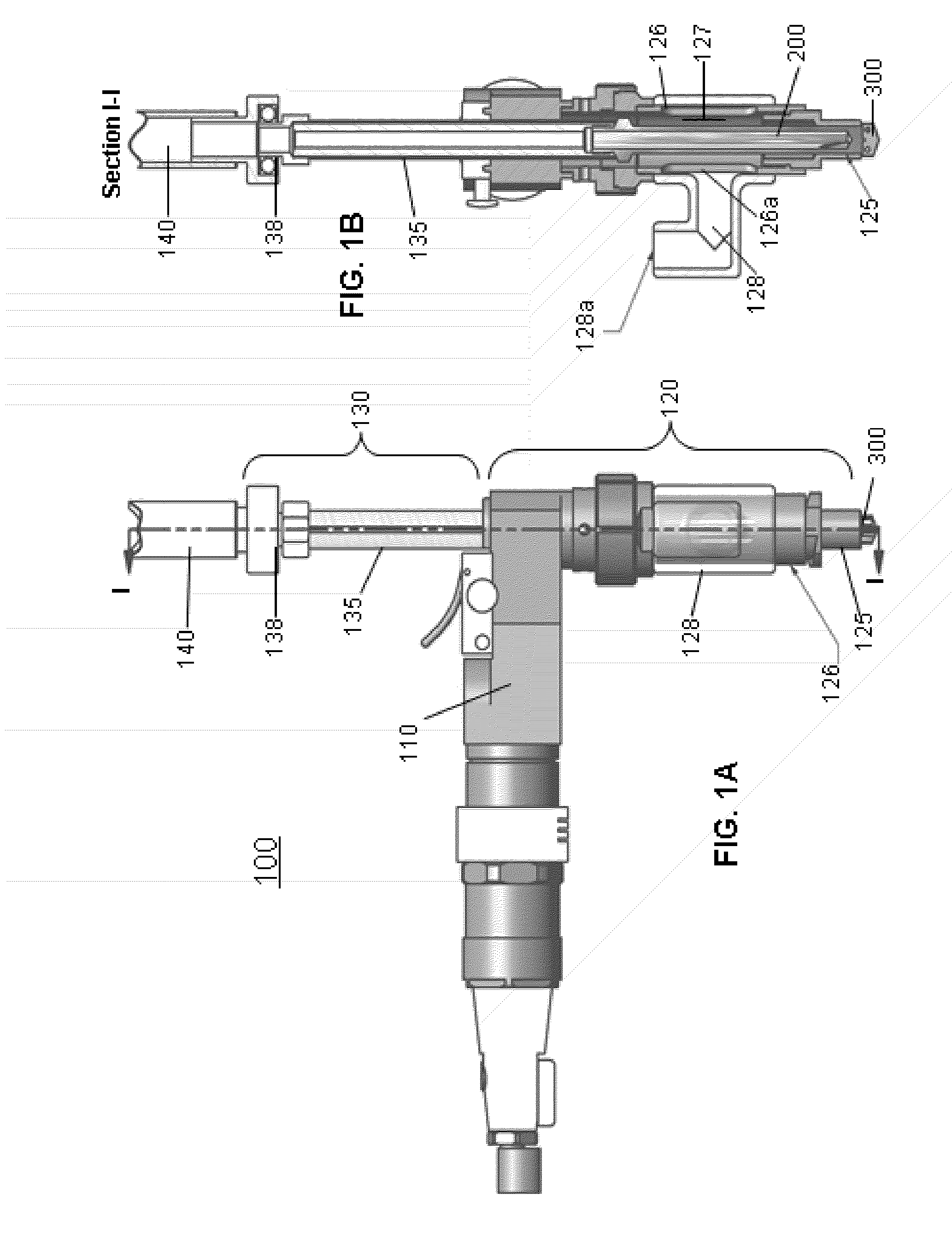
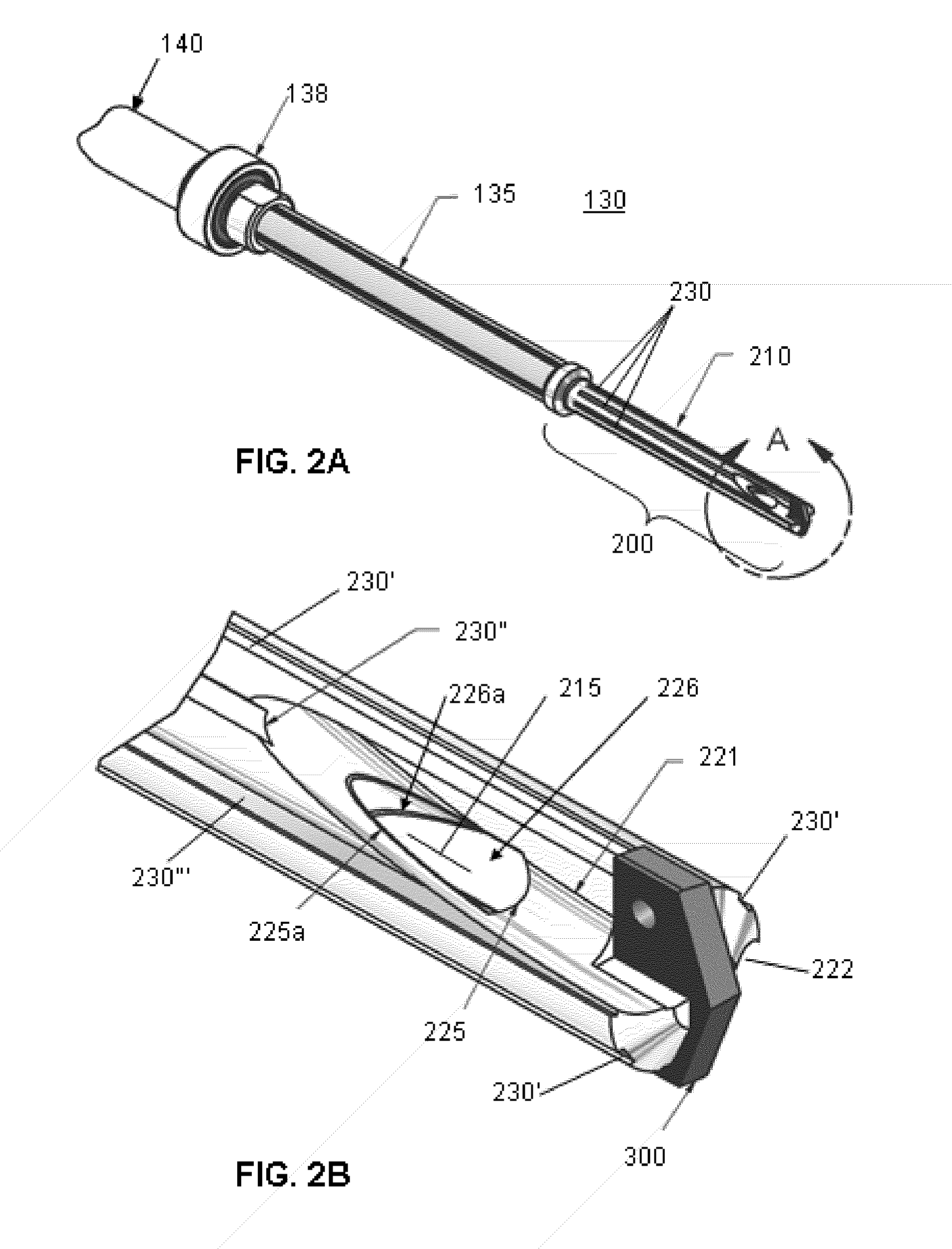
[0011]An exemplary embodiment of a vacuum drilling system 100 in accordance with the present invention is shown in FIG. 1A. A cross section I-I of the system 100 is shown in FIG. 1B. The basic configuration of the drilling system 100 is conventional, the major components thereof comprising a motor assembly 110, a nosepiece assembly 120 and a spindle assembly 130. The spindle assembly 130 is also shown isometrically, in isolation, in FIG. 2A. The spindle assembly 130 comprises a spindle 135 and a drill bit 200 coupled to one end of the spindle 135 and in axial alignment therewith. The drill bit 200 is preferably removably coupled to the spindle 135, such as by complementary threads or other suitable coupling, to allow replacement of the drill bit 200.

[0012]When the drilling system 100 is in its assembled state, the spindle assembly 130 is seated in the nosepiece assembly 120 and is radially secured thereby. The spindle assembly 130 can rotate about its axis relative to the nosepiece ...


PUM

PropertyMeasurementUnit
pressureaaaaaaaaaa
circumferenceaaaaaaaaaa
diameteraaaaaaaaaa

Abstract

An improved vacuum drilling system and drill bit includes a generally hollow vacuum drill bit with one or more chip inlets arranged proximate to one or more cutting surfaces. The drill bit also includes grooves along its exterior. When the drill bit is guided by a bushing or guide hole, the grooves serve to reduce the friction therebetween. The grooves can also convey air for cooling and improved chip collection.

Description

FIELD OF THE INVENTION[0001]The present invention relates to the field of drilling, and in particular, to vacuum drilling systems, which provide for the collection of chips generated by the drilling process.BACKGROUND INFORMATION[0002]The drilling of various materials often generates chips which, unless conveyed away from the cutting features of the drill bit, can impede the drilling process. Certain materials, including composite materials such as carbon fiber reinforced plastic (CFRP), for example, are notorious for yielding large quantities of fine chips when drilled. Without effective removal of the chips thus generated, chip compaction often occurs, reducing the drill's ability to cut, increasing the generation of heat, and reducing the life of the drill. It is not uncommon for drill bits to be discarded after drilling only five holes or less in materials such as CFRPs.[0003]Several arrangements for removing drill chips have been developed, including vacuum drilling systems, fo...

Claims


Application Information

Patent Timeline
Patent Type & Authority Patents(United States)
IPC IPC(8): B23B47/34
CPCB23B51/06B23B2251/50B23B2251/68B23B2260/072Y10T408/896Y10T408/453Y10T408/455Y10T408/50Y10T408/56245
Inventor KESTERSON, MATTHEW GDELAND, JAMES A
Owner THE BOEING CO
Why Eureka
Try Eureka