
Transformer

a transformer and transformer technology, applied in the field of transformers, can solve the problems of increasing the thickness of the product, increasing the cost, and keeping the volume of the transformer small, and achieve the effects of reducing cost, small volume, and high power

Inactive Publication Date: 2010-05-13
DELTA ELECTRONICS INC
View PDF5 Cites 14 Cited by
  • Summary
  • Abstract
  • Description
  • Claims
  • Application Information

AI Technical Summary

Benefits of technology

[0009]The objective of this invention is to overcome the drawbacks of the prior art by providing a transformer with a high power but a small volume and remarkably reduced cost.
[0010]The transformer of this invention has a plurality of printed circuit boards (PCBs) stacked with each other, wherein each of the PCBs is formed with a spiral printed circuit. Adjacent printed circuits are connected in series to form a coil so that the clearance between the windings is minimized to decrease the power loss, improve the efficiency and reduce the size.
[0011]Depending on the characteristics of the individual coils, the thickness of the printed circuits may be selectively increased to sustain a larger current and a higher voltage to meet the requirements of safety distance. Pins are made of phosphor bronze with good conductivity and moderate hardness, and are formed with an enlarged end to improve the flatness necessary for mounting on the surface of the transformer to ensure the feasibility and stability for high operation current. The pins are preferably coated with a silver layer on the surfaces thereof to enhance the conductivity of the pins. The square pads may be used on the top PCB while other PCBs may be provided with circular pads to control a better safety distance and wiring arrangement.

Problems solved by technology

To accommodate for the multiple windings and turns for conducting strong operating currents, it is difficult to keep the volume of the transformer small, thereby increasing the thickness of the product.
Furthermore, the large number of molds, complex assembly processes and lower level of automation result in increased costs.

Method used


Image

  • Transformer
  • Transformer
  • Transformer

Examples


Embodiment Construction

[0017]Hereinafter, the embodiments of this invention will be described with reference to the attached drawings.

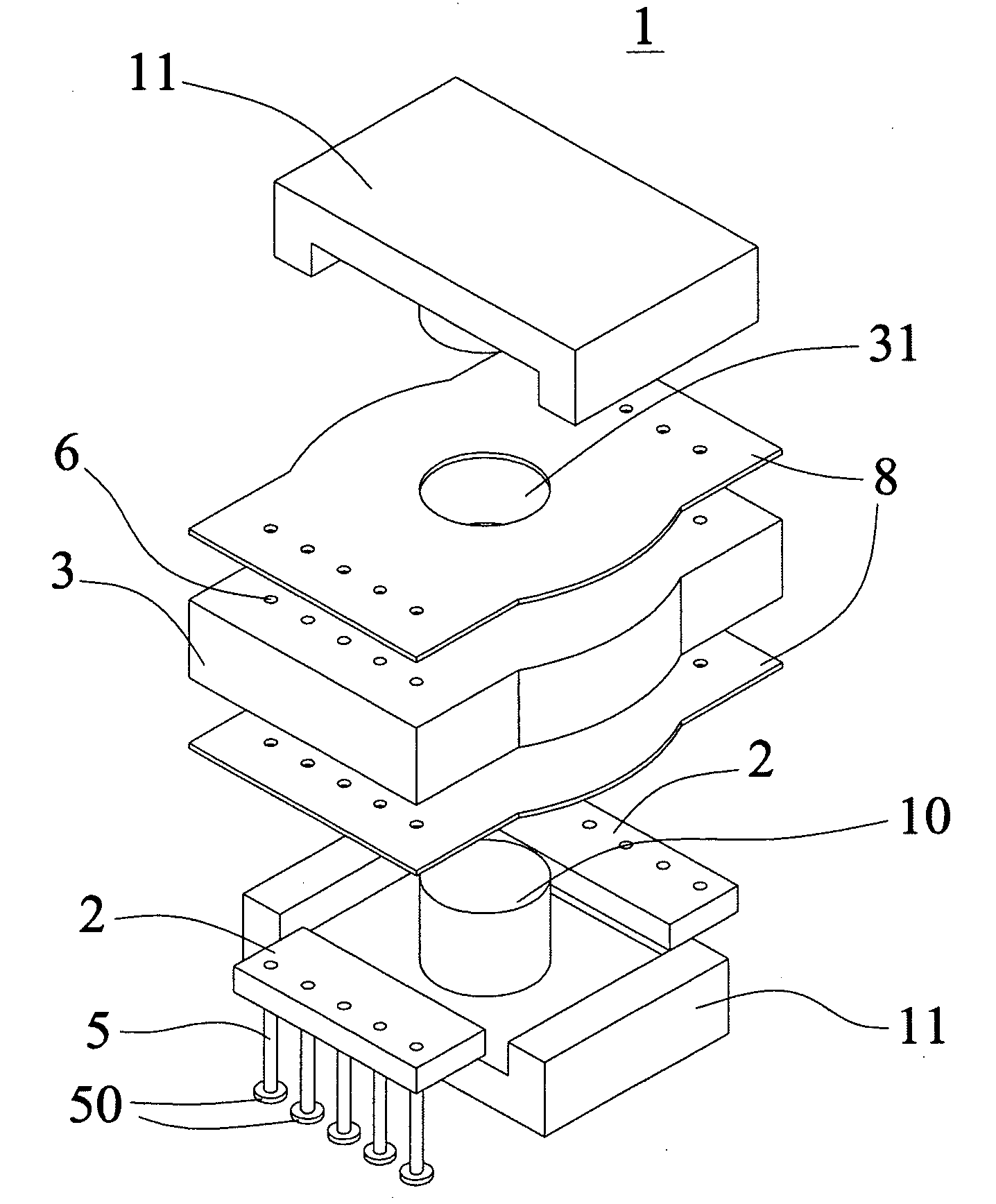
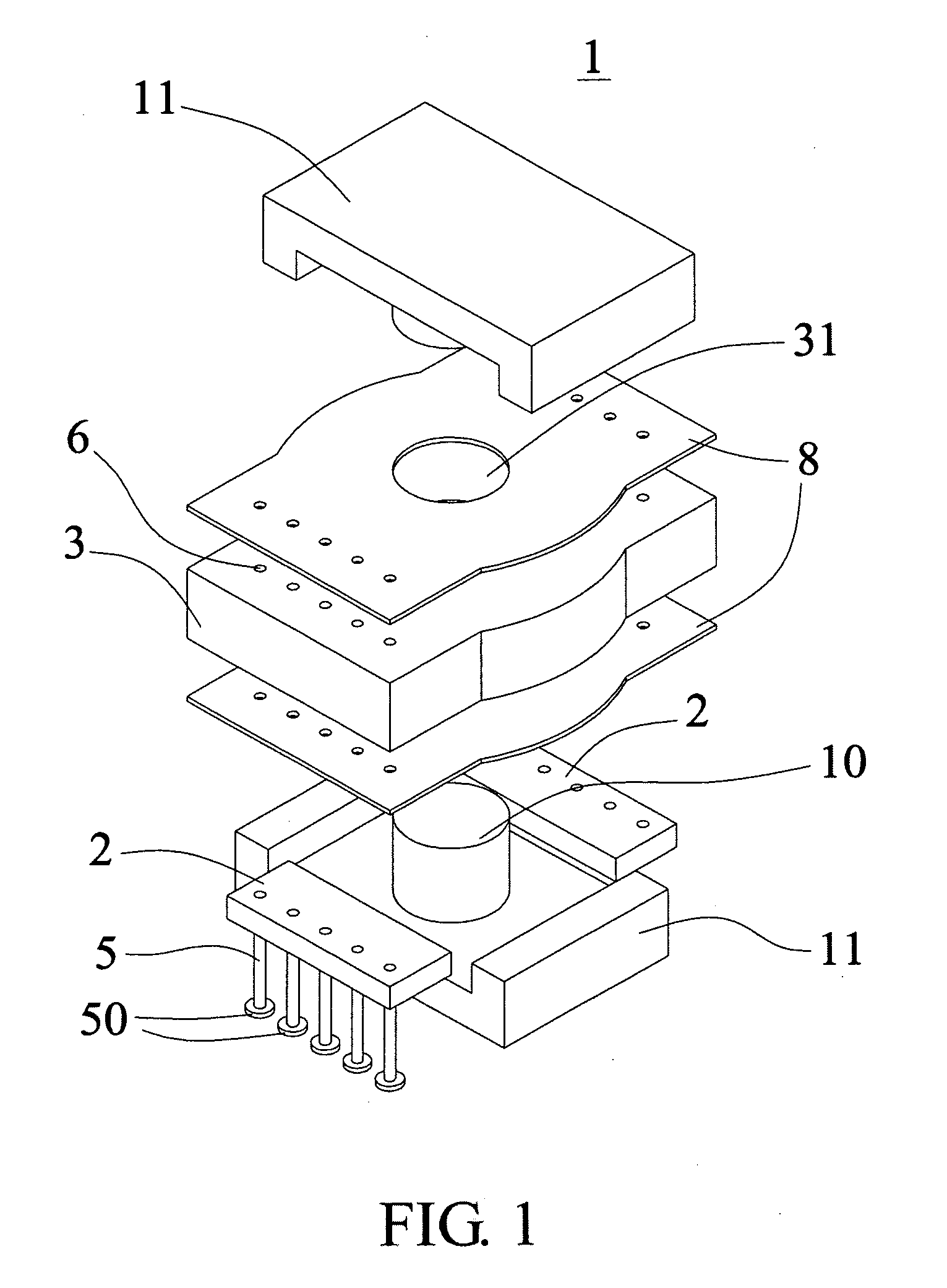
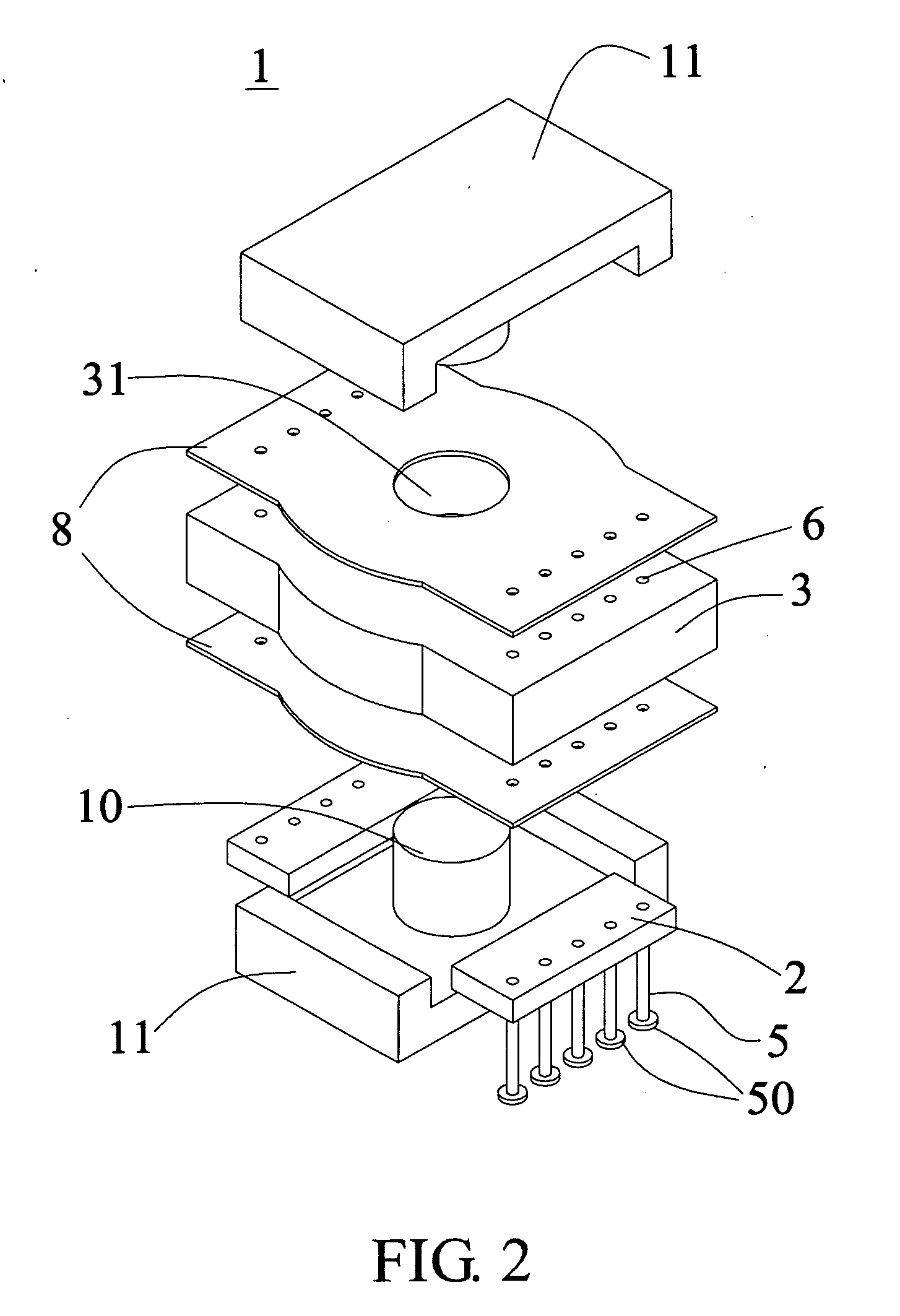
[0018]FIGS. 1 and 2 are schematic exploded views of a transformer 1 with high efficiency but a small volume. The transformer 1 comprises a core 10 penetrating through the through-hole 31 of a coil module 3. Two bases 11 are respectively connected to the two opposite ends of the core 10 to clamp the coil module 3. In this embodiment, the bases 11 and the core 10 are integrally formed.

[0019]The coil module 3 of this invention consists of a plurality of printed circuit boards (PCBs) which are electrically connected and sequentially stacked. Each of the PCBs is formed with a printed circuit, which extends spirally with respect to the core 10 and is electrically connected to the printed circuits of the adjacent PCB according to the design to form a plurality of coils sequentially stacked. Furthermore, each of the coils is formed by connecting the printed circuits of a plurality ...


PUM

PropertyMeasurementUnit
conductiveaaaaaaaaaa
insulatingaaaaaaaaaa
volumeaaaaaaaaaa

Abstract

A transformer that comprises a coil module, a core and two bases is provided. The core penetrates through the coil module. The two bases are respectively disposed on the opposite ends of the core to clamp the coil module. The coil module comprises a plurality of coils which are sequentially stacked. Each of the coils includes a plurality of PCBs which are electrically connected and sequentially stacked. Each of the PCBs is formed with a printed circuit in a spiral configuration with respect to the core. Each of the coils is formed by the electrically connected print circuits which are formed on the adjacent PCBs. Thus, the present invention provides a transformer with high efficiency and slimness.

Description

[0001]This application claims the benefits of the priority based on Taiwan Patent Application No. 097220016 filed on Nov. 7, 2008, the disclosure of which is incorporated herein by reference in its entirety.CROSS-REFERENCES TO RELATED APPLICATIONS[0002]Not applicable.BACKGROUND OF THE INVENTION[0003]1. Field of the Invention[0004]The present invention provides a transformer with high efficiency but a small volume.[0005]2. Descriptions of the Related Art[0006]As electronic technologies advance rapidly, the high-frequency transformers applied in various fields such as communication power supplies, base stations, DC-DC converters and the like are evolving towards smaller volume and higher power.[0007]Conventional transformers are typically wound with flat wires, copper sheets or aluminum sheets plus insulation sheets. In conventional transformer structure, insulation sheets must be used between adjacent windings for insulation purposes. To accommodate for the multiple windings and turn...

Claims


Application Information

Patent Timeline
Patent Type & Authority Applications(United States)
IPC IPC(8): H01F5/00H01F27/06
CPCH01F19/00H01F2027/2819H01F27/292H01F27/2804
Inventor TAN, TOPXU, YL
Owner DELTA ELECTRONICS INC
Learn More