Mechanical torque limiter

A torque limiter, mechanical technology, applied in the direction of mechanical equipment, brake type, automatic brake, etc., can solve the problems of slow braking effect and loose parts.

Pending Publication Date: 2018-10-19
JIANGXI FEIDA ELECTRICAL EQUIP
View PDF0 Cites 2 Cited by
  • Summary
  • Abstract
  • Description
  • Claims
  • Application Information

AI Technical Summary

Problems solved by technology

[0005] The purpose of the present invention is to provide a mechanical torque limiter to solve the problems of slow braking effect and easy loosening of parts in the above-mentioned background technology

Method used


Image

  • Mechanical torque limiter
  • Mechanical torque limiter
  • Mechanical torque limiter

Examples


Embodiment Construction

[0021] The following will clearly and completely describe the technical solutions in the embodiments of the present invention with reference to the accompanying drawings in the embodiments of the present invention. Obviously, the described embodiments are only some, not all, embodiments of the present invention. Based on the embodiments of the present invention, all other embodiments obtained by persons of ordinary skill in the art without making creative efforts belong to the protection scope of the present invention.

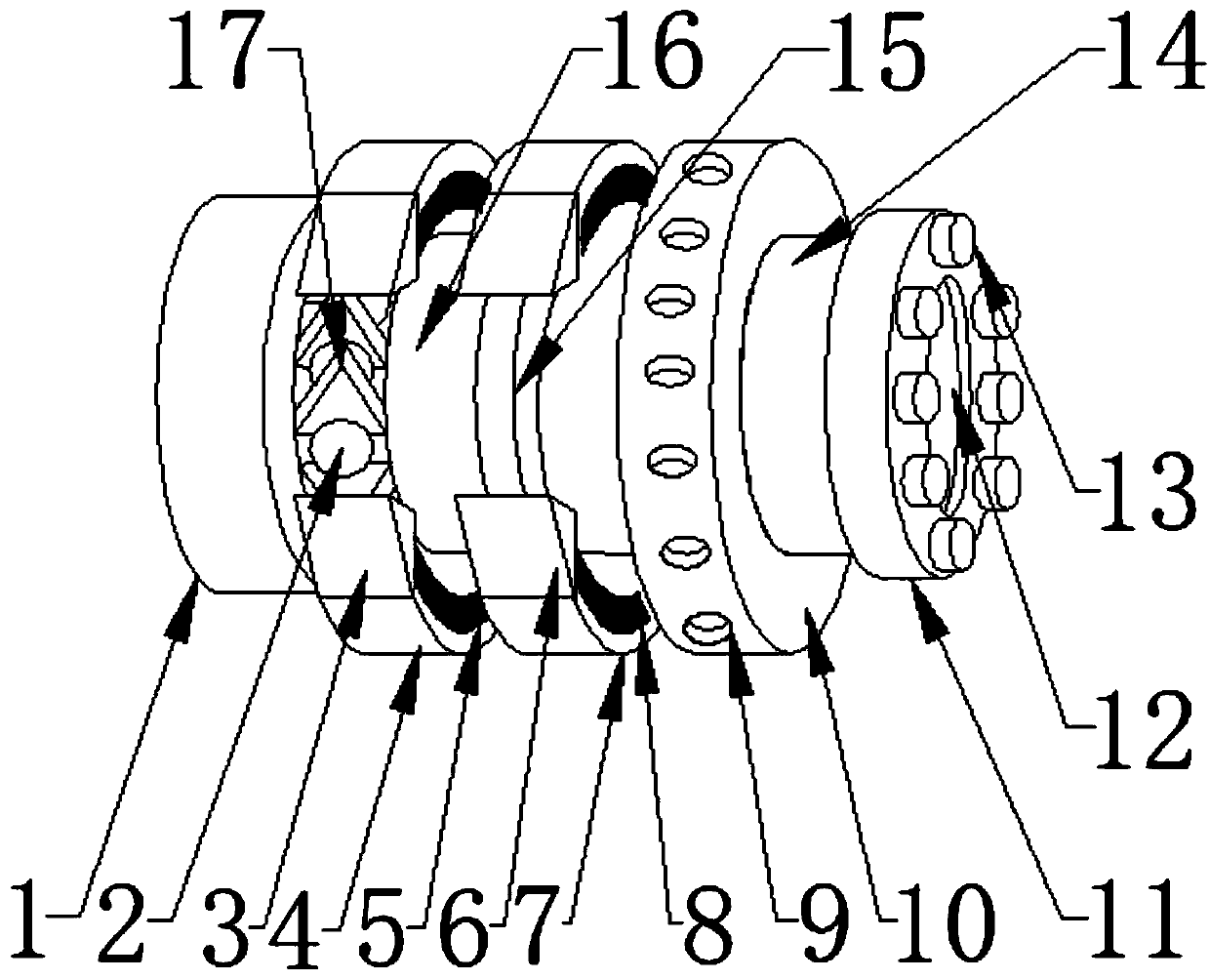
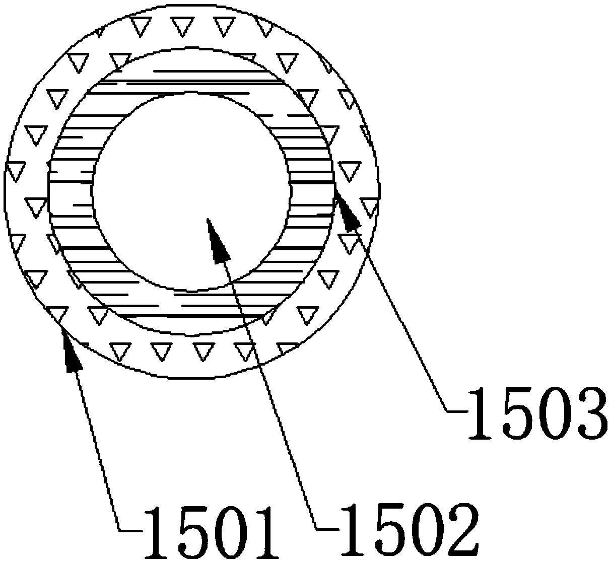
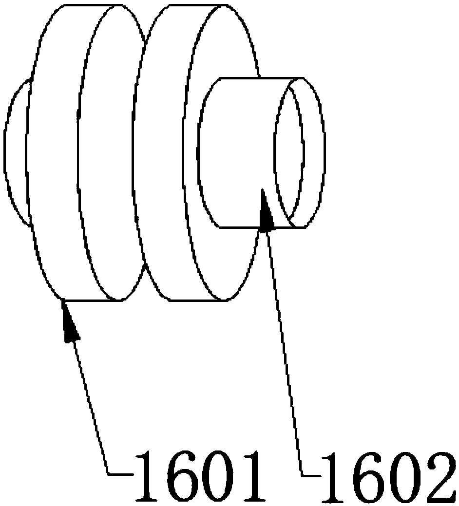
[0022] see Figure 1-3 , the present invention provides a technical solution: a mechanical torque limiter, including a driving shaft 1, a ball 2, a limiting plate 3, a brake ring 4, a movable spring 5, a brake plate 6, an imprisoning ring 7, a disc spring 8. Fixing hole 9, adjusting nut 10, nesting shaft 11, nesting ring 12, fixing anchor 13, rotating shaft 14, friction plate 15, speed limiting ring 1501, rotating shaft 1502, locking circlip 1503, flange 16. ...


PUM


Abstract

The invention discloses a mechanical torque limiter which comprises a driving shaft. A flange plate is arranged on one side of the driving shaft; braking rings, balls and locking gears are arranged onthe side face of the flange plate; the locking gears are evenly distributed on the side face of the flange plate; friction plates are arranged on one side of the flange plate, and confinement rings are arranged on the side faces of the friction plates; braking pieces are arranged at the two ends of the confinement rings; the locking gears are arranged in a triangular mode, and meanwhile the locking gears are tightly welded to the side face of the flange plate; limiting pieces are arranged at the two ends of the braking rings and formed by stainless steel alloys which are machined, and a texture is arranged at one end of each limiting piece; and meanwhile, the limiting pieces are fixedly connected with the braking rings, and the limiting pieces are arranged at the two ends of the braking rings correspondingly. When a device is braked, the limiting pieces at the two ends are inwards buckled tightly simultaneously, and through friction with the locking gears, the device is stopped in a forced mode.

Description

technical field [0001] The invention relates to the technical field of mechanical brake equipment, in particular to a mechanical torque limiter. Background technique [0002] The limiter limits some parameters of the machine to ensure the normal operation of the machine within the limited parameter values, and does not allow over-limit use. The purpose of the limiter is to maintain the safe and stable operation of the generator and avoid abnormal shutdown due to the action of the protective relay. [0003] However, the vast majority of existing mechanical torque limiters have too few braking parts and slow response of the braking parts when the device is braking, resulting in too slow braking effect of the device. If the vibration is too large when moving, it is easy to move the device parts. [0004] Therefore, how to design a mechanical torque limiter has become a problem we need to solve at present. Contents of the invention [0005] The object of the present inventi...

Claims


Application Information

Patent Timeline
Patent Type & Authority Applications(China)
IPC IPC(8): F16D59/00
CPCF16D59/00
Inventor 欧阳建华徐海红易淑红杨小香
Owner JIANGXI FEIDA ELECTRICAL EQUIP
Why Eureka
Try Eureka