A transmission mechanism and gene sequencer

A technology of transmission mechanism and transmission components, applied in the direction of transmission devices, mechanical equipment, electric components, etc., can solve the problems of stepper motor damage, failure to obtain feedback, large motor, etc., to reduce friction, improve service life and movement The effect of precision

Active Publication Date: 2021-10-22
GUANGZHOU JINQIRUI BIOTECHNOLOGY CO LTD
View PDF9 Cites 0 Cited by
  • Summary
  • Abstract
  • Description
  • Claims
  • Application Information

AI Technical Summary

Problems solved by technology

This installation method has higher requirements on the actual operating staff. The tension of the adjusted synchronous belt is different for different installations or different installations by the same person. Too small to cause tooth wear or slipping due to insufficient friction, which directly affects the transmission accuracy of the transmission mechanism and the life of the synchronous belt
[0004] In addition, the traditional transmission mechanism relies on controlling the number of pulses of the stepping motor to control the movement, but due to the influence of external factors, such as structural crawling, out-of-step phenomenon may occur, resulting in the target moving parts not reaching Predetermined position, and then can not get feedback, resulting in interference, impact and other failures
In some precision equipment, stepper motors with encoder functions are usually used to detect whether there is a step-out phenomenon, but such motors are often large or long, and are not suitable for other precision devices that require volume. equipment
And in the debugging process of instrument production, if the moving parts are reset from the farthest end, the traditional transmission mechanism needs to send multiple pulses to the stepper motor, and the waiting time for the position is very long
If the moving parts are manually pulled, the stepper motor will follow the rotation due to the traction of the synchronous belt, which may cause damage to the stepper motor

Method used


Image

  • A transmission mechanism and gene sequencer
  • A transmission mechanism and gene sequencer
  • A transmission mechanism and gene sequencer

Examples


Embodiment Construction

[0042] The following will clearly and completely describe the technical solutions in the embodiments of the present invention with reference to the accompanying drawings in the embodiments of the present invention. Obviously, the described embodiments are only some, not all, embodiments of the present invention. Based on the embodiments of the present invention, all other embodiments obtained by persons of ordinary skill in the art without creative efforts fall within the protection scope of the present invention.

[0043] In the description of the present invention, it should be understood that the orientation or positional relationship indicated by the terms "upper", "lower", "left", "right" etc. is based on the orientation or positional relationship shown in the drawings, and is only for It is convenient to describe the present invention and simplify the description, but does not indicate or imply that the device or element referred to must have a specific orientation, be co...


PUM


Abstract

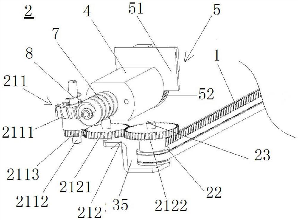
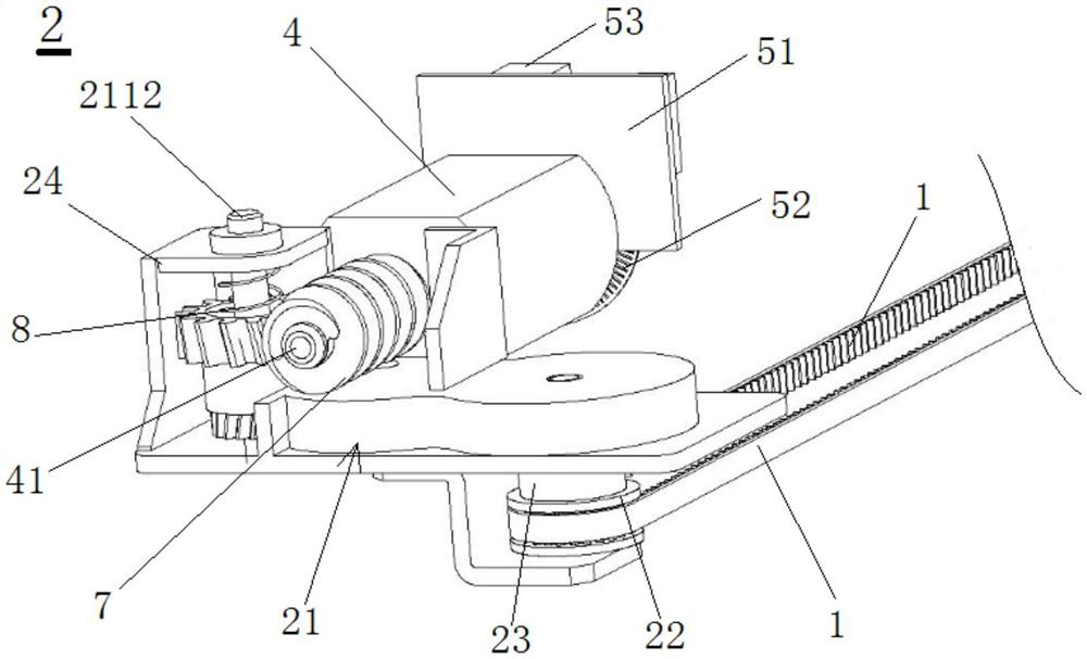
The invention provides a transmission mechanism and a gene sequencer, which are characterized in that they include an active transmission assembly, a driven transmission assembly, a synchronous belt, a drive motor, a control device, and a connecting seat for connecting a sample needle assembly; the driven transmission The assembly includes a first mount, a driven wheel, an elastic member and a second mount for fixed installation on the gene sequencer, and the elastic member is fixedly connected between the first mount and the second mount; the drive transmission assembly includes a gear The device and the driving wheel, the second end of the synchronous belt is sleeved on the driving wheel; the arrangement direction of the elastic member is consistent with the arrangement direction of the synchronous belt; the connecting seat is fixedly connected to one side of the synchronous belt; the driving motor and the control device electrical connection. Its working precision is high, and it can reduce and eliminate the difference in the tension of the synchronous belt and the crawling phenomenon caused by human factors during the installation process, reduce motion wear and prolong the service life.

Description

technical field [0001] The invention relates to the field of in vitro diagnostic automated medical equipment, in particular to a transmission mechanism and a gene sequencer. Background technique [0002] Gene sequencer is a kind of automatic medical equipment for in vitro diagnosis. During its working process, the precise loading of samples or reagents is an essential and important part before diagnosis, which determines the quality and reliability of test results. Therefore, in practical applications The precision requirements for automatic loading devices for samples or reagents are very high. Among them, the transmission mechanism is usually used in the position where precise loading is required, which can directly affect the accuracy of the automatic loading device. [0003] During the assembly process of traditional transmission mechanisms used in automatic sample or reagent loading devices, parts other than the driven wheel mechanism often need to be fixed first, and ...

Claims


Application Information

Patent Timeline
Patent Type & Authority Patents(China)
IPC IPC(8): F16H37/12H02K7/116C12Q1/6869
CPCC12Q1/6869F16H37/12H02K7/1166
Inventor 区仲荣陈嘉昌胡朝晖柳俊陈述卿
Owner GUANGZHOU JINQIRUI BIOTECHNOLOGY CO LTD
Why Eureka
Try Eureka