
Bridge crack detection device based on cableway

A technology for detection devices and bridges, which is applied in the directions of measuring devices, cable railways, transportation and packaging, etc., can solve the problems of detection devices that cannot be detected, fixed camera monitoring range is limited, strain gauge detection system is complicated, etc., to expand the scope of application, comprehensive Detection effect

Inactive Publication Date: 2014-10-01
CHONGQING JIAOTONG UNIVERSITY
View PDF11 Cites 0 Cited by
  • Summary
  • Abstract
  • Description
  • Claims
  • Application Information

AI Technical Summary

Problems solved by technology

[0003] In the prior art, most detection devices use strain gauges, fixed cameras, etc. In addition, the detection system of strain gauges is relatively complicated, and the monitoring range of fixed cameras is limited. Under these conditions, commonly used detection devices cannot perform real-time and comprehensive detection

Method used


Image

  • Bridge crack detection device based on cableway
  • Bridge crack detection device based on cableway

Examples


Embodiment Construction

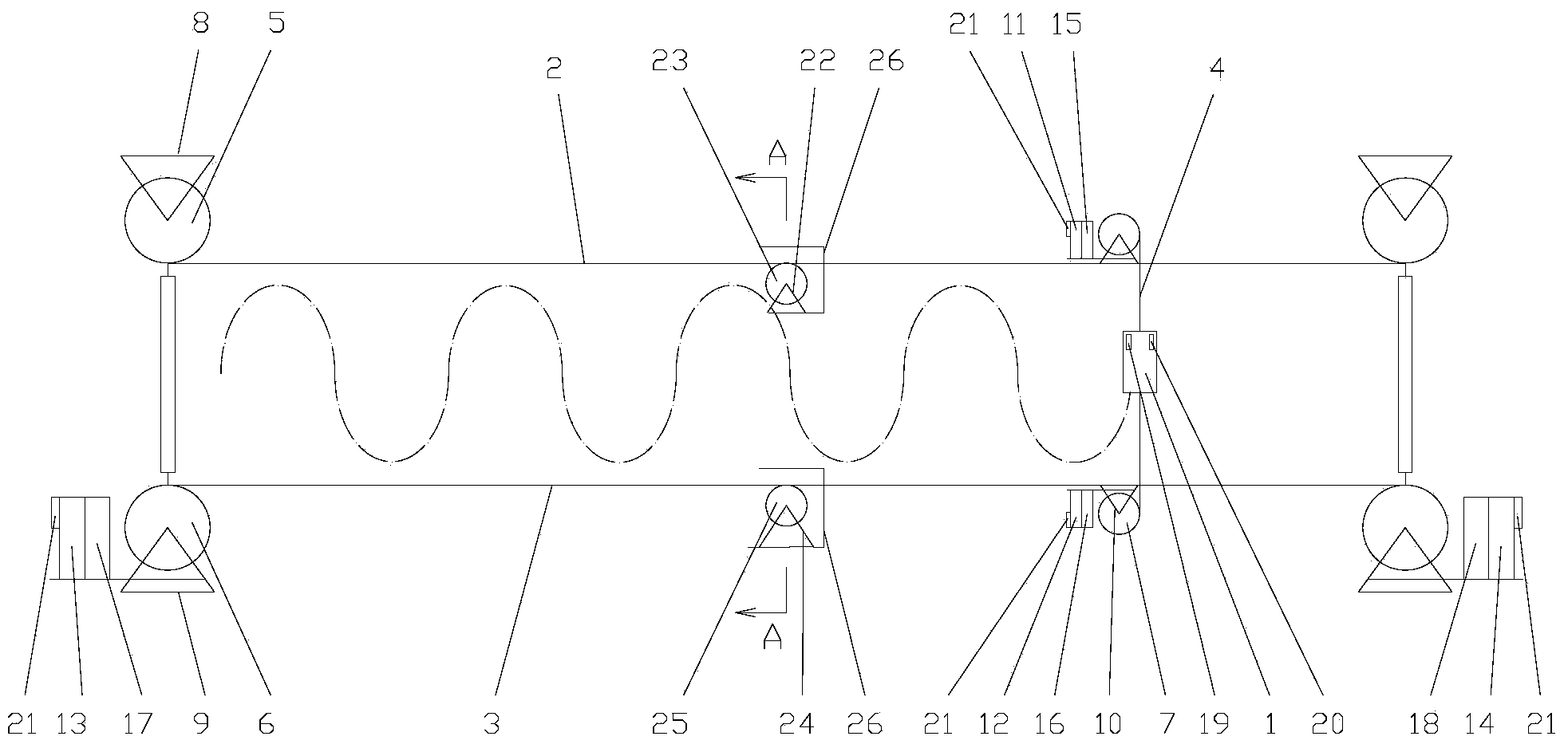
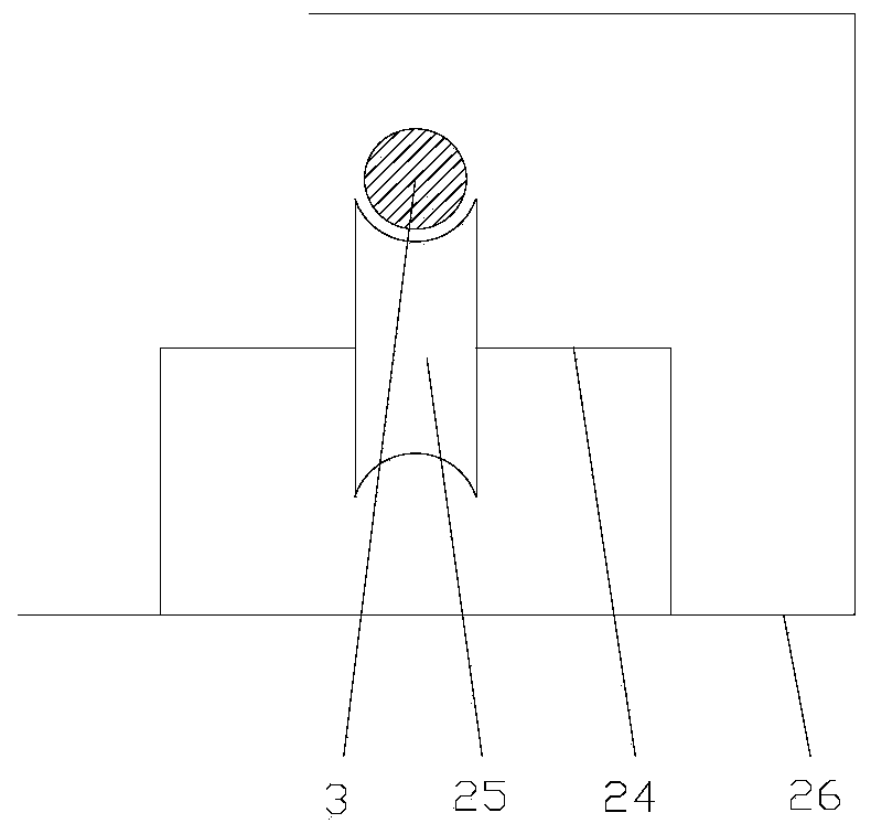
[0017] figure 1 It is a structural schematic diagram of the present invention, figure 2 It is the A-A sectional view, as shown in the figure: the bridge crack detection device based on the cableway of the present embodiment includes a detection device 1, a vertical guide wire, a horizontal guide wire and is used to drive the vertical guide wire and the horizontal guide wire The power unit assembly of the cable; the detection device 1 is fixed on the vertical guide cable and driven to move vertically by the vertical guide cable, and the vertical guide cable is installed on the horizontal guide cable and driven horizontally by the horizontal guide cable Movement, through the coordinated operation of the horizontal guide rope and the vertical guide rope, the detection device 1 can be moved along a wave-shaped trajectory, and a large-capacity micro-camera is used as the detection device 1 to save real-time detection data of bridges and buildings. It is convenient for the later i...


PUM


Abstract

The invention discloses a bridge crack detection device based on a cableway. The bridge crack detection device comprises a detection device, a vertical guide cable, a horizontal guide cable and a power device assembly for dividing the vertical guide cable and the horizontal guide cable; the detection device is fixed on the vertical guide cable and driven by the vertical guide cable to move vertically; the vertical guide cable is mounted on the horizontal guide cable and driven by the horizontal guide cable to move horizontally. The bridge crack detection device based on the cableway is designed on a side surface of a bridge so that the detection device is capable of realizing more comprehensive real-time detection in case of relatively long span of the bridge and the like, and therefore, the application range of the detection device is expanded.

Description

technical field [0001] The invention relates to a detection device, in particular to a bridge crack detection device based on a cableway. Background technique [0002] In order to test the working performance of many products, testing devices are often used to test their working process and working effect, so as to find the defects of products and projects, and improve the quality of later working products. However, in some special applications, higher requirements are placed on the detection device. To a certain extent, the detection effect of the detection device directly determines the use effect of the product. [0003] In the prior art, most detection devices use strain gauges, fixed cameras, etc. In addition, the detection system of strain gauges is relatively complicated, and the monitoring range of fixed cameras is limited. Under these conditions, commonly used detection devices cannot perform real-time and comprehensive detection. [0004] Therefore, there is a n...

Claims


Application Information

Patent Timeline
IPC IPC(8): B65G35/00B61B7/00G01B21/02
Inventor 罗天洪陈才马翔宇郭园马力
Owner CHONGQING JIAOTONG UNIVERSITY
Learn More