
Control devices for spark ignition engines

A spark ignition type, control device technology, applied in the direction of engine control, engine components, combustion engine, etc., can solve the problems of pressure rise, combustion noise increase, etc.

Inactive Publication Date: 2016-04-20
MAZDA MOTOR CORP
View PDF7 Cites 0 Cited by
  • Summary
  • Abstract
  • Description
  • Claims
  • Application Information

AI Technical Summary

Problems solved by technology

However, compression ignition combustion is a combustion in which the pressure rises sharply as the engine load increases, leading to an increase in combustion noise

Method used


Image

  • Control devices for spark ignition engines
  • Control devices for spark ignition engines
  • Control devices for spark ignition engines

Examples


Embodiment Construction

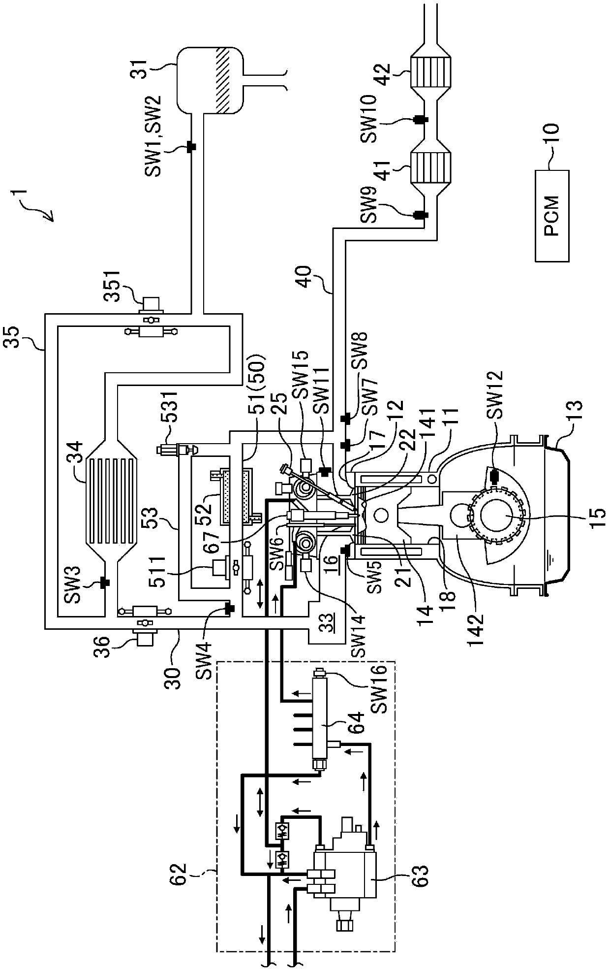
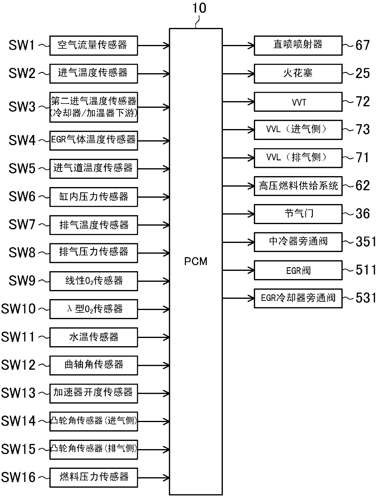
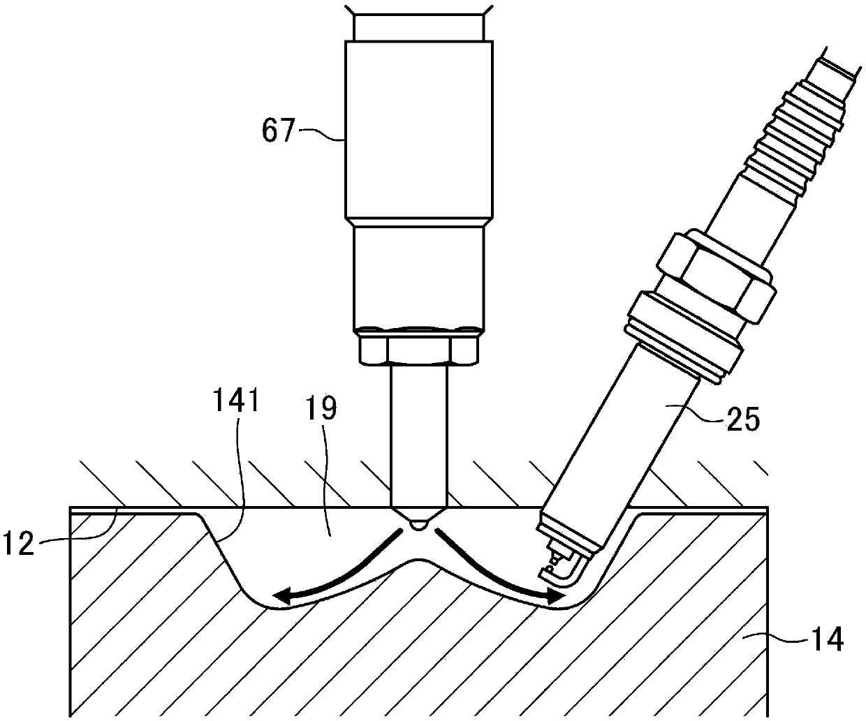
[0062] Next, an embodiment of a spark ignition type direct injection engine will be described based on the drawings. The description of the following preferred embodiments is an illustration. figure 1 , figure 2 A schematic structure of the engine (engine main body) 1 is shown. The engine 1 is a spark ignition type gasoline engine mounted on a vehicle and supplied with fuel including at least gasoline. The engine 1 has a cylinder block 11 provided with a plurality of cylinders 18 (in addition, although in figure 1 Only one cylinder is shown in the figure, but for example, four cylinders can be arranged in series), the cylinder head 12 arranged on the cylinder block 11, and the oil sump arranged on the lower side of the cylinder block 11 for storing lubricating oil shell13. A piston 14 connected to the crankshaft 15 via a connecting rod 142 is reciprocally inserted into each cylinder 18 . On the top surface of the piston 14, such as image 3 As shown enlarged in the midd...


PUM


Abstract

The invention provides a control device for a spark ignition engine. When switching from the spark ignition mode to the compression ignition mode, the control device (10) sequentially executes the first step of setting the air-fuel ratio (A / F) of the mixture to a specified value and performing spark ignition combustion, so that the air-fuel ratio (A / F) of the mixture The second step is to perform compression ignition combustion when the fuel ratio is leaner than the first step, and the third step is to make the air-fuel ratio of the air-fuel mixture richer than the second step to perform compression ignition combustion.

Description

technical field [0001] The technology disclosed in this invention relates to control devices for spark ignition engines. Background technique [0002] For example, as described in Patent Document 1, there is known a combustion form in which the air-fuel mixture in the cylinder is compressed and ignited as a technique for achieving both improvement in exhaust emission performance and improvement in thermal efficiency. However, the compression ignition combustion is a combustion in which the pressure rises rapidly as the load on the engine increases, leading to an increase in combustion noise. Therefore, as described in Patent Document 1, even in an engine that performs compression ignition combustion, in a high-load operating range, generally, compression ignition combustion is not performed, but spark ignition combustion driven by a spark plug is performed. [0003] Patent Document 2 describes that, similarly to the engine of Patent Document 1, in an engine that performs co...

Claims


Application Information

Patent Timeline
Patent Type & Authority Patents(China)
IPC IPC(8): F02D43/00
CPCF02B29/0437F02D13/0207F02D13/0265F02D41/0057F02D41/3023F02D41/3035F02D41/3064F02D41/402F02D2041/001F02D2041/3052F02M31/04F02M26/01F02M26/25F02M26/28Y02T10/12Y02T10/40F02D41/3011
Inventor 高桥敏彰田贺淳一岩井浩平
Owner MAZDA MOTOR CORP
Learn More