A kind of anti-loosening structure

An anti-loose and card board technology, applied in the direction of protective switch terminals/connections, electromagnetic relay details, relays, etc., can solve problems such as poor contact, arc generation, and easy loosening of conductive metal plates, and achieve the effect of preventing loosening and deformation.

Active Publication Date: 2017-01-18
XIAMEN HONGFA ELECTRICAL SAFETY & CONTROLS CO LTD
View PDF4 Cites 0 Cited by
  • Summary
  • Abstract
  • Description
  • Claims
  • Application Information

AI Technical Summary

Problems solved by technology

[0004] Due to the opening on the side of the accommodating cavity, a slot is formed on the front side wall of the accommodating cavity, and at the same time, a through hole is formed on the top of the accommodating cavity, so that the overall strength of the accommodating cavity is weak, and the components installed in the accommodating cavity The conductive metal plate of the terminal is easy to loose, resulting in poor contact or arcing

Method used


Image

  • A kind of anti-loosening structure
  • A kind of anti-loosening structure
  • A kind of anti-loosening structure

Examples


Embodiment Construction

[0031] The present invention will be described in detail below in conjunction with the accompanying drawings and specific embodiments.

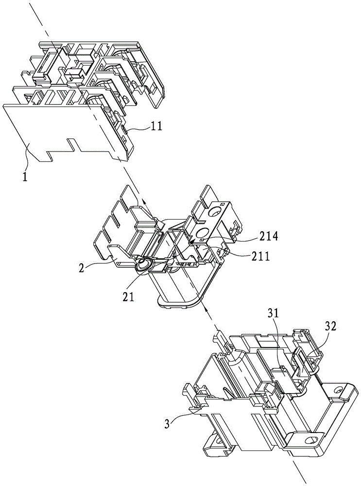
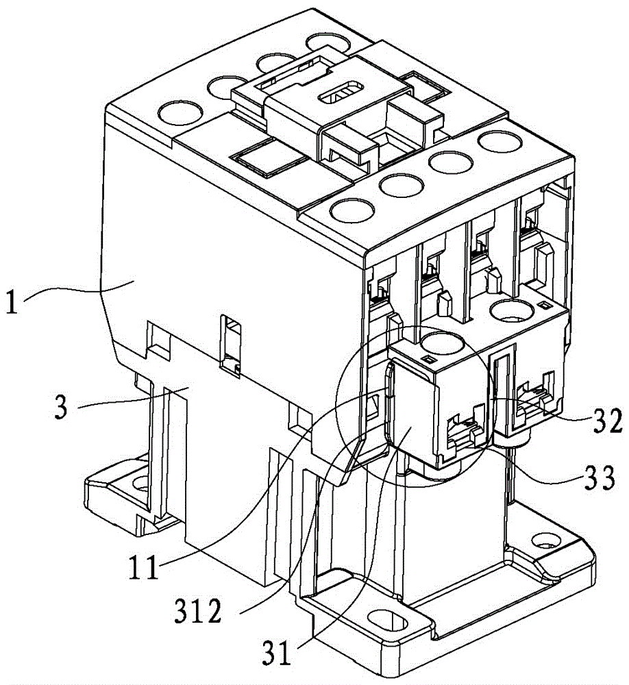
[0032] refer to Figure 1 to Figure 6 As shown, an anti-loosening structure disclosed by the present invention includes a body 1 , a bobbin 2 and a base 3 .

[0033] The coil bobbin 2 is installed in the body case 1 , and an accommodating cavity 21 is formed on the coil bobbin 2 , and an opening 211 is provided at a side of the accommodating cavity 21 .

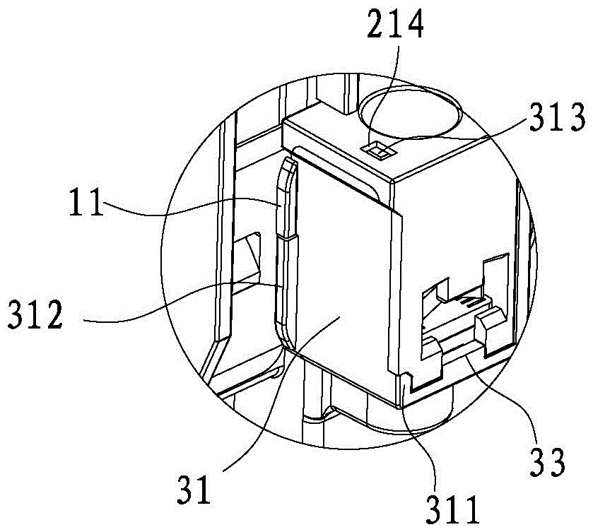
[0034] A first clamp 31 and a second clamp 32 are formed on the base 3, the body 1 is installed on the base 3, and the accommodating cavity 21 is inserted between the first clamp 31 and the second clamp 32, and the first clamp The plate 31 is inserted into the side opening 211 , and the first clamping plate 31 and the second clamping plate 32 clamp the accommodating cavity 21 .

[0035] Such as Figure 5 As shown, a locking groove 212 is formed on the side wall of the side opening 211, an...


PUM


Abstract

The invention discloses an anti-disengaging structure which comprises a body, a coil frame and a base. The coil frame is installed in the body, and a containing cavity with an opening in one side is formed in the coil frame. A first clamping plate and a second clamping plate are formed on the base, the body is installed on the base, the containing cavity is clamped between the first clamping plate and the second clamping plate, the first clamping plate is clamped in the opening, and the first clamping plate and the second clamping plate clamp the containing cavity. A clamping groove is formed in the side wall of the opening, a clamping block is formed on the first clamping plate, and the clamping block is clamped in the clamping groove. By means of the anti-disengaging structure, the containing cavity can be prevented from disengagement and deformation, and a wiring terminal conductive metal plate is effectively prevented from disengagement.

Description

technical field [0001] The invention relates to an anti-loosening structure, which is suitable for electrical equipment such as contactors and circuit breakers. Background technique [0002] In order to realize automatic assembly, an accommodation cavity is usually formed on the coil bobbin, and the side of the accommodation cavity is opened. The conductive metal plate is installed in the accommodation cavity and electrically connected with the coil. The screw is placed in the accommodation cavity through the side opening. In the accommodating cavity, a limiting mechanism that restricts the screw from falling off is formed. The limiting mechanism can be an elastic sheet, and a through hole is formed on the top of the accommodating cavity, and the through hole is used to lock the screw; the front side wall of the accommodating cavity forms a slot , the conductive metal plate is exposed, so that the probe can be directly in contact with the electric metal plate for detection d...

Claims


Application Information

Patent Timeline
Patent Type & Authority Patents(China)
IPC IPC(8): H01H50/14H01H50/44H01H71/08
Inventor 田新疆夏昌慧
Owner XIAMEN HONGFA ELECTRICAL SAFETY & CONTROLS CO LTD
Why Eureka
Try Eureka