Method for operating an electrolysis system and electrolysis system

A technology of electrolysis system and electrolysis cell, which is applied in the direction of electrolysis process, electrolysis components, cells, etc., can solve the problems of increasing the cost of electrolysis process, and achieve the effect of cost saving

Active Publication Date: 2017-04-12
SIEMENS ENERGY GLOBAL GMBH & CO KG
View PDF8 Cites 0 Cited by
  • Summary
  • Abstract
  • Description
  • Claims
  • Application Information

AI Technical Summary

Problems solved by technology

Both of these increase the cost of the electrolytic process

Method used


Image

  • Method for operating an electrolysis system and electrolysis system
  • Method for operating an electrolysis system and electrolysis system
  • Method for operating an electrolysis system and electrolysis system

Examples


Embodiment Construction

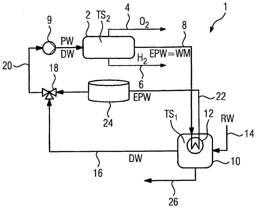
[0046] exist figure 1 An electrolysis system 1 with a PEM electrolysis cell 2 for generating hydrogen H2 and oxygen O2 is shown in . In the example shown, high-pressure electrolysis is carried out. However, the PEM electrolysis cell 2 can also be operated at atmospheric pressure.

[0047] The components of the PEM electrolysis cell 2 are a proton-permeable polymer membrane (Proton-Exchange-Membrane proton exchange membrane) not shown in detail here, which is connected on both sides to electrodes (anode, cathode) coated with catalyst. ) in contact. An external voltage is applied to the electrodes and water is delivered on the anode side of the PEM electrolysis cell 2 . Oxygen, electrons, and positively charged hydrogen ions are formed when water is split. The hydrogen ions diffuse through the proton-conducting membrane to the cathode side, where they combine by means of electrons from the external circuit to form hydrogen molecules H2. From the PEM electrolysis cell 2, the...


PUM


Abstract

Operating an electrolyzer (2) for generating hydrogen by decomposing water, comprises: storing waste heat produced within the electrolyzer in a heat transfer medium; supplying the heat transfer medium to a water treatment plant (10); and producing deionized water from raw water in the water treatment plant by the waste heat. An independent claim is also included for an electrolyzer system (1) for generating hydrogen and oxygen through electrolysis of water by the above mentioned method.

Description

technical field [0001] The invention relates to a method and an electrolysis system for operating an electrolysis system for producing hydrogen and oxygen by splitting water. Background technique [0002] The fluid can be stored in the form of hydrogen or oxygen by splitting water into hydrogen and oxygen with the aid of an electrolyte. After the reaction, most of the introduced electrical energy is recovered in the chemical energy of the products hydrogen and oxygen (die Produkte Wasserstoff und Sauerstoff). However, in addition to the products hydrogen and oxygen, losses in the form of heat of reaction also form during the electrolysis. [0003] The electrolysis process is supplied with fresh water, which is usually completely desalinated, in particular distilled, water. To prevent minerals and other impurities from coating the electrode surfaces of the electrolytic cell, tap water is cleaned and deionized even before it is delivered to the electrolytic cell. In order t...

Claims


Application Information

Patent Timeline
Patent Type & Authority Patents(China)
IPC IPC(8): C25B1/10C25B15/08
CPCC25B1/04C25B15/08C25B9/73Y02E60/36Y02P20/129
Inventor 托马斯·哈默迪特尔·莫斯特约亨·舍费尔马丁·塔肯贝格阿明·达茨克劳斯·登纳林诺贝特·胡贝尔安德烈亚斯·赖纳约亨·斯托柏维尔纳·斯托柏
Owner SIEMENS ENERGY GLOBAL GMBH & CO KG
Why Eureka
Try Eureka