Air-conditioning unit and air-conditioning unit for railway vehicle
An air-conditioning device and control device technology, applied in the heating/cooling of railway vehicles, railway car body parts, transportation and packaging, etc., can solve problems such as poor lubrication of compressors, and achieve the effect of inhibiting refrigerant stagnation
- Summary
- Abstract
- Description
- Claims
- Application Information
AI Technical Summary
Problems solved by technology
Method used
Image

Examples
Embodiment approach 1
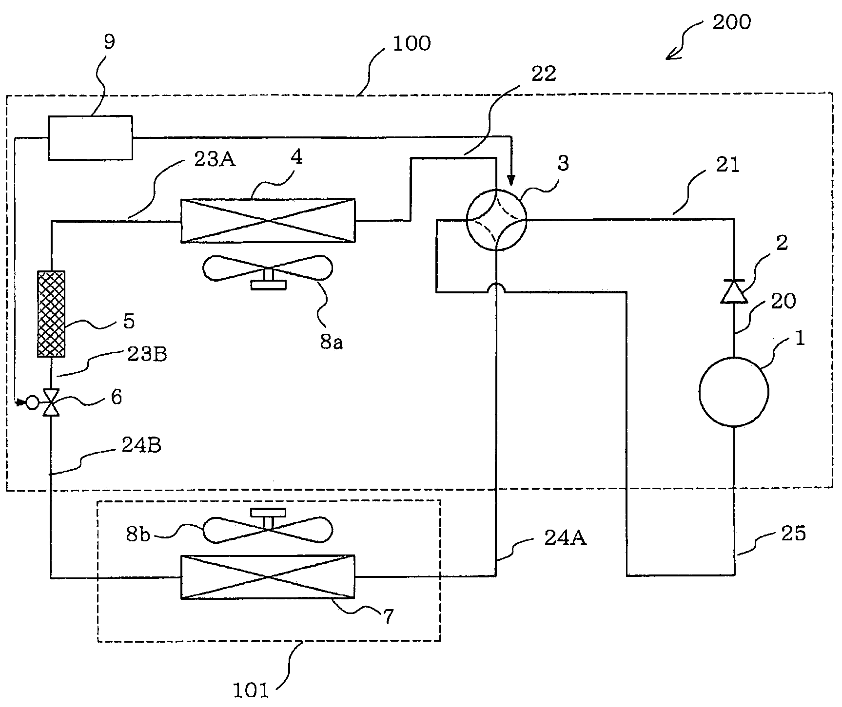
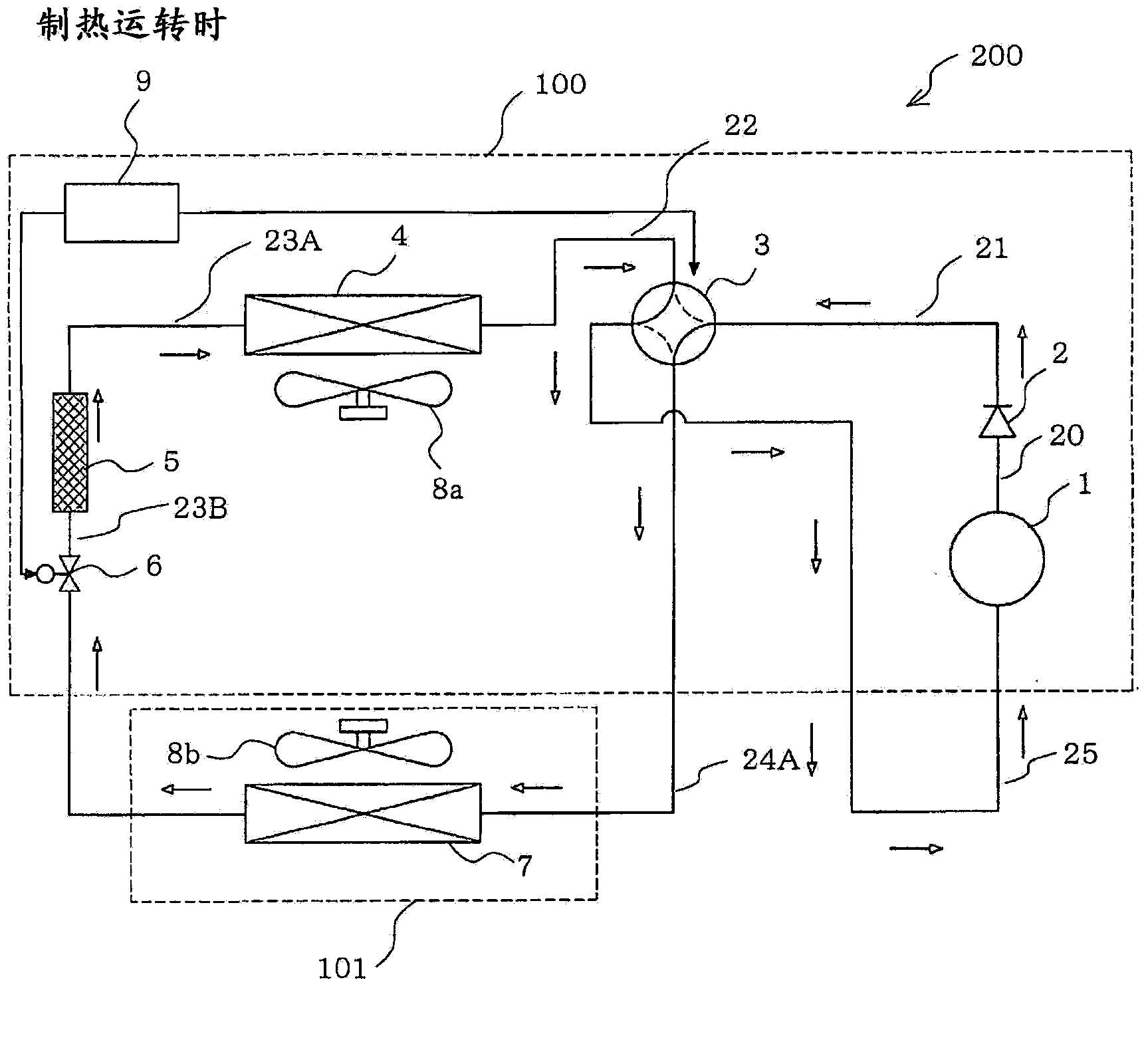
[0037] figure 1 This is an example of the refrigerant circuit configuration of the air conditioner 200 according to the first embodiment.
[0038] The air conditioner 200 according to Embodiment 1 separates the refrigerant from the lubricating oil in the compressor.
[0039] [Structure of the air conditioner 200]
[0040] The air conditioner 200 includes an outdoor unit 100 installed outside, for example, and an indoor unit 101 connected to the outdoor unit 100 through a refrigerant pipe to supply air-conditioned air to a space to be air-conditioned (for example, a room, a warehouse, etc.).
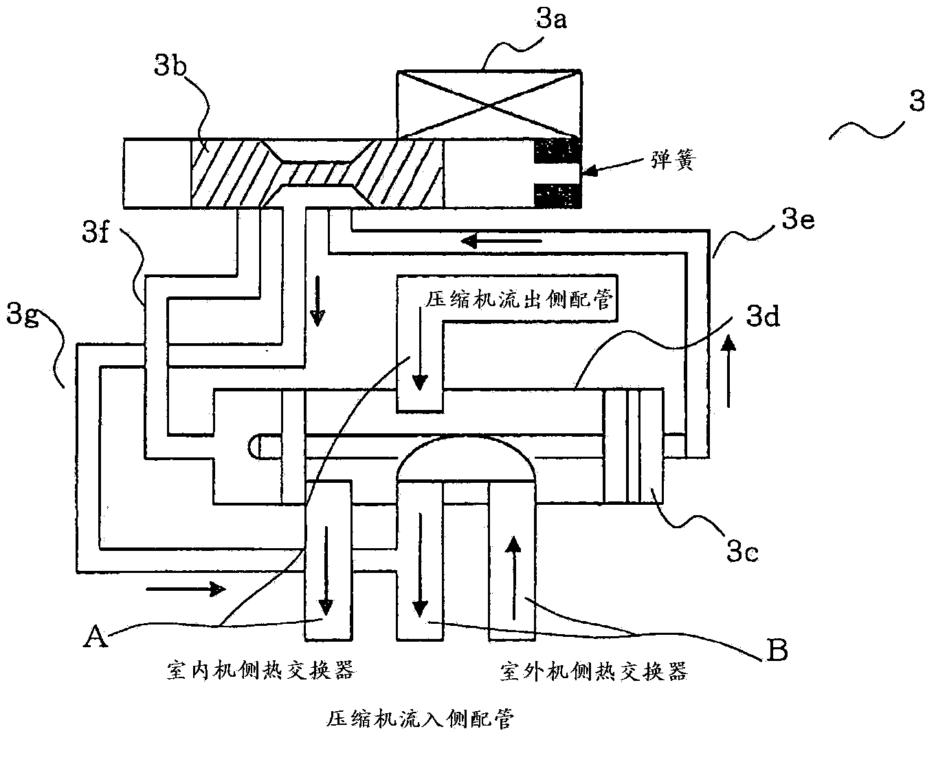
[0041] The outdoor unit 100 has: a compressor 1 that compresses and discharges refrigerant; a check valve 2 that is provided on the discharge side of the compressor 1; a four-way valve 3 that switches the flow of refrigerant; an outdoor heat exchanger 4 that function as a condenser (radiator) during cooling operation, and function as an evaporator during heating operation; the blower 8...
Embodiment approach 2
[0127] In Embodiment 2, the same reference numerals are used for the same parts as in Embodiment 1, and the differences between Embodiments 1 and 2 will be mainly described. Figure 7 This is an example of the refrigerant circuit configuration of the air conditioner 200b according to the second embodiment.
[0128] In addition to the configuration of the air conditioner 200 according to Embodiment 1, the air conditioner 200b according to Embodiment 2 is provided with a low-pressure detection means 10 for detecting pressure on a compressor inlet pipe 25 connected to the suction side of the compressor 1 . The low pressure detection means 10 may be constituted by, for example, a pressure sensor or the like. Embodiment 2 is the same as Embodiment 1 about the structure other than this.
[0129] Figure 8 It is an explanatory diagram of the control flow of the air conditioner 200b according to the second embodiment. refer to Figure 8 The operation of the control device 9 will b...
Embodiment approach 3
[0137] In Embodiment 3, the same reference numerals are used for the same parts as Embodiments 1 and 2, and the differences from Embodiments 1 and 2 will be mainly described. Figure 9 It is an example of the refrigerant circuit structure of the air-conditioning apparatus 200c which concerns on Embodiment 3. In addition to the structure of the air conditioner 200b according to the second embodiment, the air conditioner 200c according to the third embodiment is provided with a refrigerant pipe 26 connecting the connection pipe 23B and the compressor 1, and the refrigerant flowing through the refrigerant pipe 26 The expansion member 11 depressurizes the refrigerant, the solenoid valve 12 switches conduction of the refrigerant flowing through the refrigerant pipe 26 , and the temperature detection member 10A detects the temperature of the refrigerant flowing through the compressor outflow side pipe 20 .
[0138] The refrigerant pipe 26 is a pipe that connects the connecting pipe ...
PUM
 Abstract
Description
Claims
Application Information
 - R&D Engineer
- R&D Manager
- IP Professional
- Industry Leading Data Capabilities
- Powerful AI technology
- Patent DNA Extraction
Browse by: Latest US Patents, China's latest patents, Technical Efficacy Thesaurus, Application Domain, Technology Topic.
© 2024 PatSnap. All rights reserved.Legal|Privacy policy|Modern Slavery Act Transparency Statement|Sitemap