Synchronous motion device for double rotating shafts
A technology of synchronous movement and double shafts, applied in the direction of pivot connection, etc., can solve problems that have not been specifically taught or revealed, and achieve the effect of easy operation
- Summary
- Abstract
- Description
- Claims
- Application Information
AI Technical Summary
Problems solved by technology
Method used
Image

Examples
Embodiment Construction
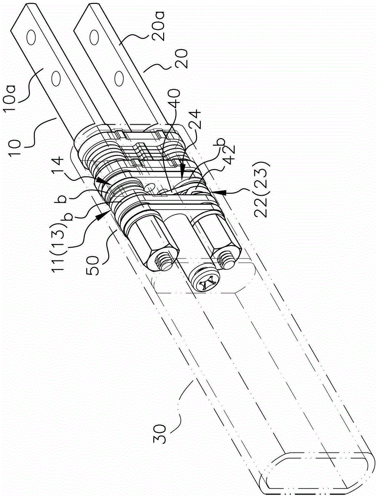
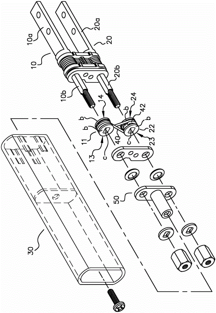
[0050] see figure 1 , figure 2 and image 3 , the synchronous motion device for dual shafts of the present invention includes a first shaft and a second shaft; these are denoted by reference numerals 10 and 20, respectively. The first shaft 10 and the second shaft 20 are assembled in a casing 30; the first and second shafts 10, 20 respectively have a fixed end 10a, 20a and a pivot end 10b, 20b. The fixed ends 10a, 20a cooperate with the fixed seat (not shown in the figure), so that the first and second axes 10, 20 are respectively fixed on the display module 91 and the body module 92 of the electronic device 90 (for example, a mobile phone, a computer, etc.) exist Figure 5 ).
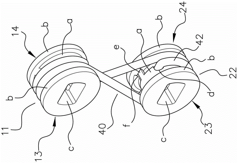
[0051] figure 1 , figure 2 and image 3 It also shows that the pivotal end 10b of the first shaft 10 is synchronously linked with the first rotor 11 (it can be directly installed on the pivotal end 10b, or indirectly drive the pivotal end 10b); the pivotal end 20b of the second shaft 20 is syn...
PUM
 Abstract
Description
Claims
Application Information
 - Generate Ideas
- Intellectual Property
- Life Sciences
- Materials
- Tech Scout
- Unparalleled Data Quality
- Higher Quality Content
- 60% Fewer Hallucinations
Browse by: Latest US Patents, China's latest patents, Technical Efficacy Thesaurus, Application Domain, Technology Topic, Popular Technical Reports.
© 2025 PatSnap. All rights reserved.Legal|Privacy policy|Modern Slavery Act Transparency Statement|Sitemap|About US| Contact US: help@patsnap.com