Double-beam delayed laser damage testing system

A technology of laser damage and testing system, which is applied in the direction of testing optical properties

Active Publication Date: 2014-10-15
SHANGHAI INST OF OPTICS & FINE MECHANICS CHINESE ACAD OF SCI
View PDF8 Cites 26 Cited by
  • Summary
  • Abstract
  • Description
  • Claims
  • Application Information

AI Technical Summary

Problems solved by technology

[0005] Although the existing patented technology introduces the laser damage threshold testing system from different aspects, and there are also patents that combine two sets of laser systems with different wavelengths into one, but there has never been a patent for the concept of double-beam delay after splitting the same pulsed laser beam Introduced into the laser damage threshold test, and most of the test systems are only suitable for lasers with pulse widths on the order of nanoseconds

Method used


Image

  • Double-beam delayed laser damage testing system
  • Double-beam delayed laser damage testing system

Examples


Embodiment Construction

[0019] The embodiments of the present invention will be further described below in conjunction with the examples and accompanying drawings, but the protection scope of the present invention should not be limited thereby.

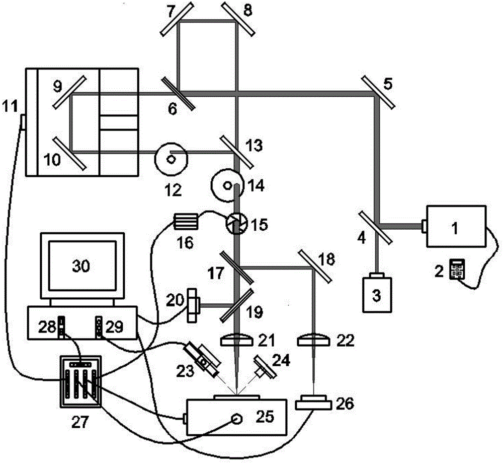
[0020] figure 1 It is a schematic diagram of the double-beam delayed laser damage testing system of the present invention, which is composed of figure 1It can be seen that the dual-beam delayed laser damage testing system of the present invention is applicable to different laser pulse widths and can realize automatic control of the system. In this system, Nd:YAG pulsed laser 1 emits a pulsed laser with a pulse width of 30 ps, ​​a peak energy of 50 mJ, a wavelength of 1064 nm, and a frequency of 10 Hz. Select continuous pulse triggering through laser controller 2, and set the laser energy attenuation to 50%. The pulse laser passes through the first reflector 4 and the second reflector 5 with a center wavelength of 1064nm to the first beam splitter 6, and th...


PUM


Abstract

The invention discloses a double-beam delayed laser damage testing system. The system is composed of a pulse laser, a laser controller, seven reflecting mirrors, four light splitters, two annular changeable neutral-density filtering sheets, an electrically controlled translation platform, a motor driver, a main control computer, an electronic shutter, two plano-convex lenses, a three-dimensional electrically controlled sample platform, a beam quality analyzer, an energy detector, a high-resolution color CCD imaging device and a white light source. With the utilization of the computer, the double-beam delayed laser damage testing system realizes automatic control by utilizing the computer, and can perform laser damage threshold testing of lasers in different pulse widths on the surface of an optical element.

Description

technical field [0001] The invention relates to laser damage testing of optical components, in particular to a double-beam delayed laser damage testing system. Background technique [0002] Optical components such as optical films are indispensable basic components in laser systems, and they are also one of the weakest links in the entire system. Optical components used in high-energy and high-power laser systems are required to work stably for a long time, or the performance of the system will not be significantly reduced. However, after optical components are irradiated by laser light, even if there are very small defects, the quality of the output beam will be reduced, and at the same time, it will cause damage to subsequent components, and in severe cases, the entire system will be paralyzed. The anti-laser damage characteristics of optical components will directly affect the design of the entire system and the performance of the system operation. Therefore, the problem...

Claims


Application Information

Patent Timeline
Patent Type & Authority Applications(China)
IPC IPC(8): G01M11/02
Inventor 赵元安李泽汉李大伟
Owner SHANGHAI INST OF OPTICS & FINE MECHANICS CHINESE ACAD OF SCI
Why Eureka
Try Eureka