Supercharge Your Innovation With Domain-Expert AI Agents!

Exhaust system of internal combustion engine

An exhaust system, internal combustion engine technology, applied in the direction of internal combustion piston engine, charging system, combustion engine, etc., can solve the problems of insufficient meshing, the power of the electric motor is not effectively transmitted, etc.

Inactive Publication Date: 2017-10-27
DENSO CORP
View PDF7 Cites 0 Cited by
  • Summary
  • Abstract
  • Description
  • Claims
  • Application Information

AI Technical Summary

Problems solved by technology

Therefore, due to the axial misalignment of the eccentric shaft, insufficient meshing is caused between the intermediate gear and the output gear
Therefore, there is a problem that the power of the electric motor is not effectively transmitted to the eccentric wheel and the poppet valve.

Method used


Image

  • Exhaust system of internal combustion engine
  • Exhaust system of internal combustion engine
  • Exhaust system of internal combustion engine

Examples


no. 1 example )

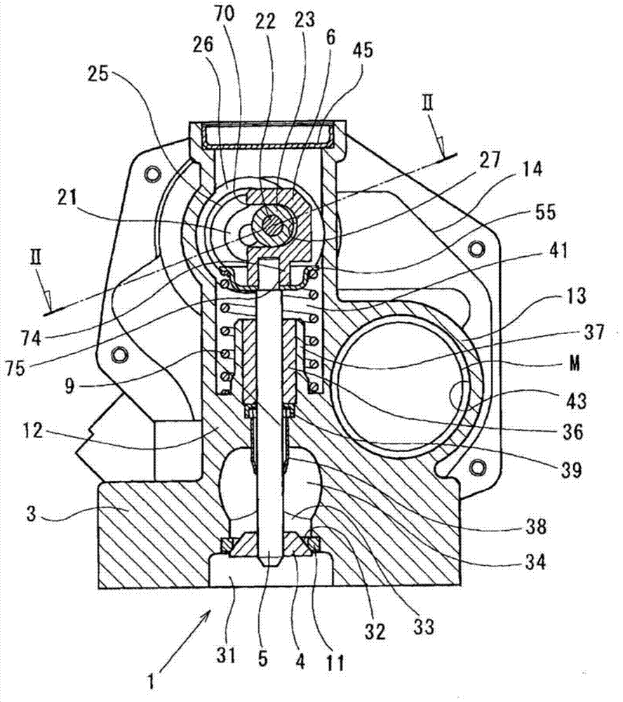
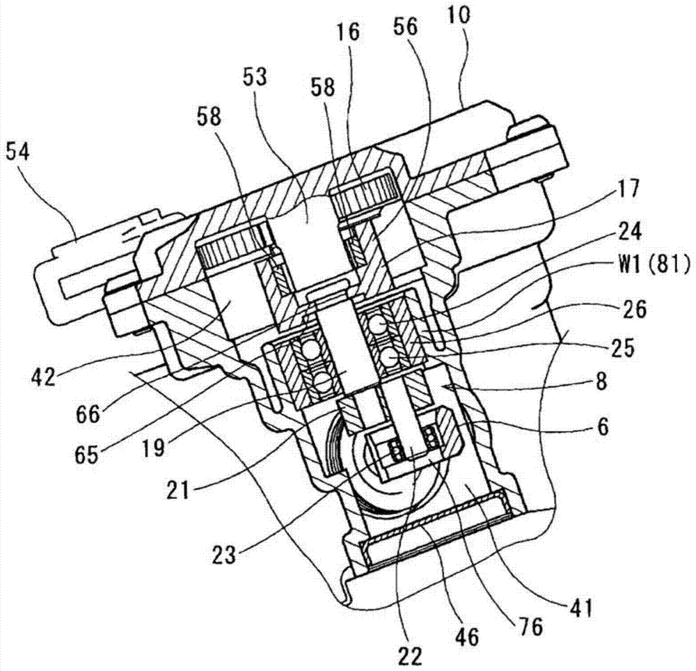
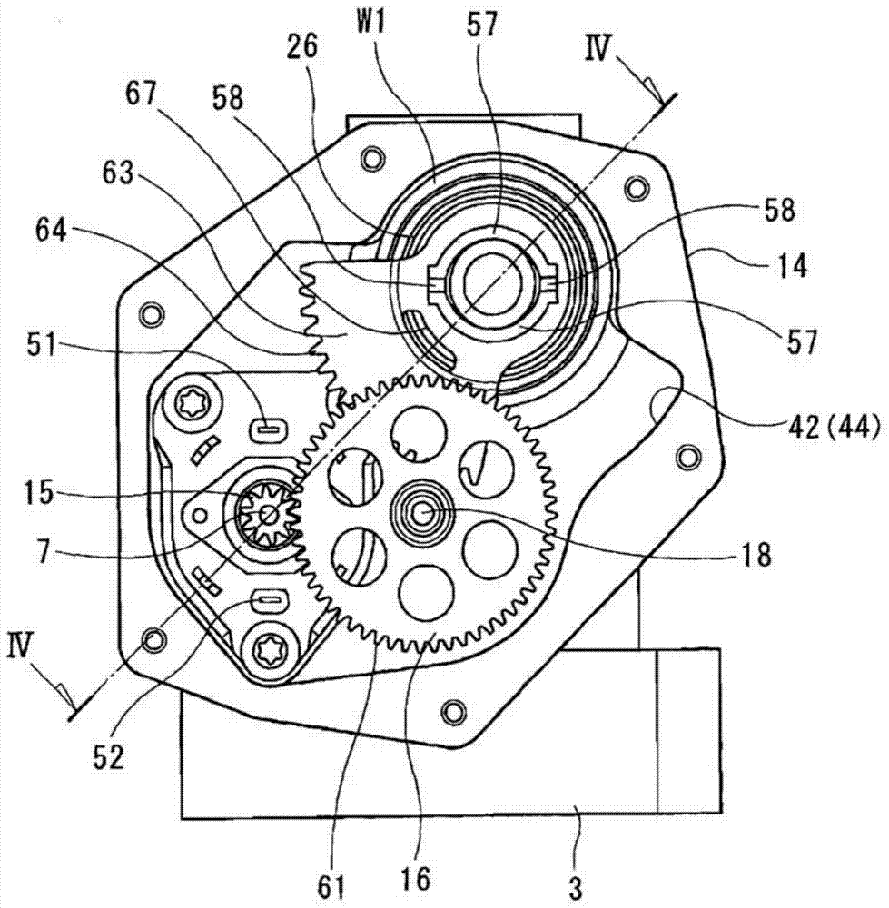
[0027] The configuration of the exhaust system for an internal combustion engine of the first embodiment will be described below. Figures 1 to 11 The EGR control valve of the first embodiment is shown, and the control valve is used in an exhaust gas recirculation system (EGR system) of an engine to which the present invention is applied.

[0028] The exhaust system of the engine of this embodiment includes an exhaust gas recirculation system (hereinafter referred to as EGR system) for transferring exhaust gas (hereinafter referred to as EGR gas) from an internal combustion engine (multi-cylinder diesel engine: hereinafter referred to as The exhaust duct of the engine recirculates (flows back) into the intake duct. The EGR system includes an EGR gas pipe for returning EGR gas from an exhaust manifold or an exhaust passage in an exhaust pipe to an intake manifold or an intake passage in an intake pipe. An EGR gas flow passage through which EGR gas flows from the exhaust passag...

no. 2 example )

[0106] The configuration of the EGR control valve of the second embodiment will be described below. Figures 12 to 15 An EGR control valve of a second embodiment is shown, which is used in an exhaust gas recirculation system (EGR system) of an engine to which the present invention is applied. The same reference numerals as those of the first embodiment denote the same or corresponding configurations or functions, and explanations thereof will be omitted.

[0107] Similar to the first embodiment, the link mechanism of the actuator 2 of the present embodiment includes a yoke 6 , an output rod 21 , a pivot pin 22 and a follower 23 . Upon receiving the rotational power of the motor M from the pivot pin 22 through the follower 23, the yoke 6 reciprocates in the axial direction of the valve stem 5, and the fitting portion 74 is press-fitted to the end of the valve stem 5 in the axial direction thereof. Proximal part (input part). Therefore, the yoke 6 is connected to the EGR valve...


PUM


Abstract

In an exhaust system for an internal combustion engine, an output element (8) is configured to transmit power generated by a motor (M) to a switch element (4) via a valve stem (5). The output shaft (19) is arranged on the rotation center axis of the output gear (17) and combined with the output gear (17) so as to be integrally rotatable therewith. The follower (23) is arranged eccentrically with respect to the rotation center axis of the output shaft (19) and is connected to the output shaft (19) so as to be integrally rotatable therewith. The first accommodation chamber (41) at least accommodates the valve stem (5) and the follower (23). The second accommodating cavity (42-44) at least accommodates the motor (M) and the output gear (17). The housing (3) comprises housing walls (W1, W2) separating the first chamber (41) from the second chamber (42-44). The housing walls (W1, W2) include first bearings (24, 25) that slidably support the output shaft (19) in its direction of rotation and cylindrical first bearings (24, 25) that hold the outer periphery of the first bearings (24, 25). Bearing retainer (81).

Description

technical field [0001] The present disclosure relates to exhaust systems for internal combustion engines. In particular, the present disclosure relates to exhaust gas recirculation systems for internal combustion engines (engines). Background technique [0002] Generally, for an exhaust system of an internal combustion engine, for example, there is known an exhaust gas recirculation system (EGR system) which recirculates exhaust gas (hereinafter referred to as EGR gas) from an exhaust pipe into an internal combustion engine through an exhaust gas recirculation pipe ( engine) to reduce harmful substances (for example, nitrogen oxides, NOx) contained in exhaust gas discharged from cylinders of an engine driving a vehicle such as a motor vehicle. [0003] In the EGR system, an EGR gas flow rate control valve (hereinafter referred to as an EGR control valve) is arranged for variably controlling the flow rate of EGR gas flowing through the EGR flow passage in the exhaust gas rec...

Claims


Application Information

Patent Timeline
Patent Type & Authority Patents(China)
IPC IPC(8): F02M26/54F16K31/04
CPCF02M26/54F02M26/68F02M26/53F02M26/55F02M26/56F02M26/57F02M26/58F02M26/67Y02T10/12
Inventor 佐野亮石垣聪岛田广树佐藤修
Owner DENSO CORP
Features
  • R&D
  • Intellectual Property
  • Life Sciences
  • Materials
  • Tech Scout
  • Unparalleled Data Quality
  • Higher Quality Content
  • 60% Fewer Hallucinations
Learn More