Optical material transmittance testing system and testing method thereof

A test system and test method technology, applied in the direction of transmittance measurement, etc., can solve the problems of sample thickness limitation, inability to guarantee accuracy, small light receiving range, etc.

Inactive Publication Date: 2014-10-22
BRIGHT CRYSTALS TECH
View PDF13 Cites 3 Cited by
  • Summary
  • Abstract
  • Description
  • Claims
  • Application Information

AI Technical Summary

Problems solved by technology

[0004] use figure 1 In the test method shown, the light emitted by the light source 1 is perpendicular to the sample 2 under test, and the incident light passes through the sample under test and then enters the detector 3 along the propagation direction of the original incident light. However, this method can only test that the sample 2 under test receives vertical light. Penetrating properties of radiation; using figure 2 and image 3 In the test method shown, the light emitted by the light source 1 is transmitted at a certain angle relative to the surface of the tested sample 2, and after being refracted by the tested sample 2, it is transmitted towards the direction of the detector 3. Light receiving range is small, such as figure 2 and image 3 As shown, in the common system, the detector 3 can only receive a part of the incident light or even can not receive the incident light at all, these systems have certain restrictions on the thickness of the sample when using angled incident test
[0005] Therefore, the optical material transmittance test method in the common system of the prior art cannot guarantee the accuracy of the transmittance measurement when there is an angled incidence to the sample to be tested, and is no longer suitable for the transmittance test of the optical material, and the angled incidence The time transmittance test method is an important way to improve the research and development speed of optical materials, so it is necessary to improve the existing test methods to complete the accurate test of the spectral transmittance of optical materials at angled incidence

Method used


Image

  • Optical material transmittance testing system and testing method thereof
  • Optical material transmittance testing system and testing method thereof
  • Optical material transmittance testing system and testing method thereof

Examples


Embodiment Construction

[0034] In order to make the object, technical solution and advantages of the present invention clearer, the present invention will be described in detail below with reference to the accompanying drawings and specific embodiments.

[0035] The test system for optical material transmittance described in specific embodiments of the present invention includes:

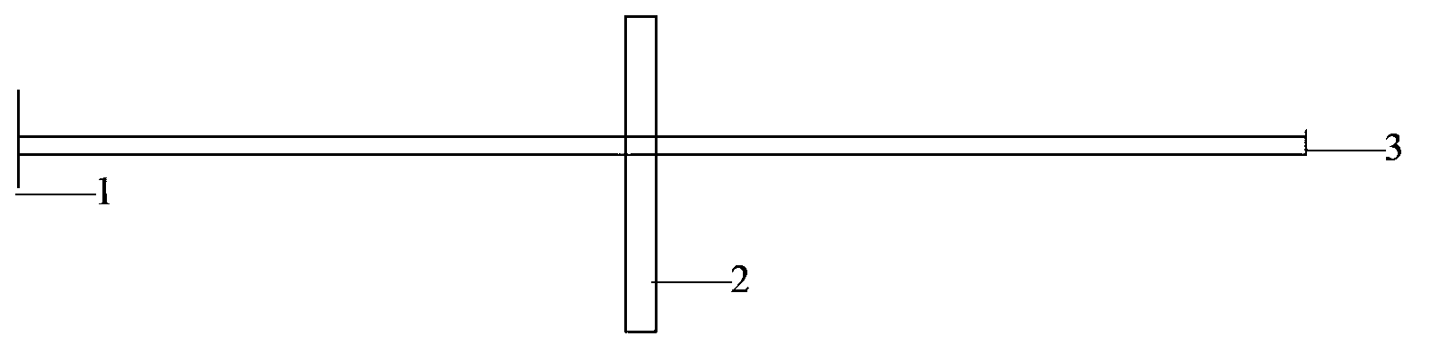
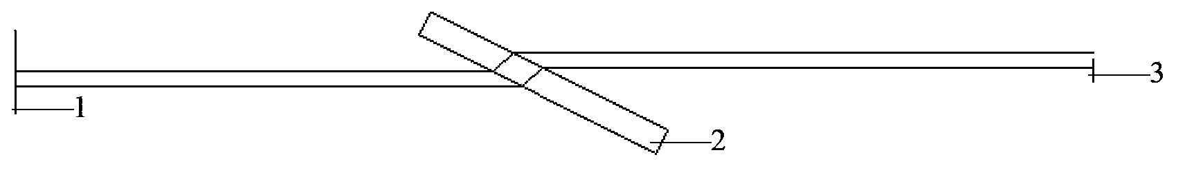
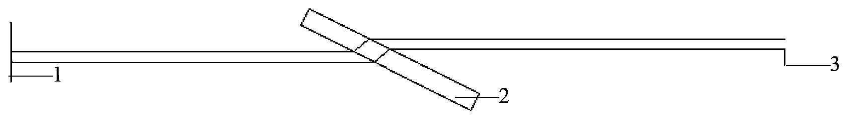
[0036] A light source for providing transmittance test irradiation light, the light source emits light along a first direction to obtain incident light for testing;

[0037] At least two tested samples, the first tested sample is used to receive the incident light, and the incident light is at an angle relative to the surface of the first tested sample, and the incident light passes through the first tested sample Obtain the first refracted light after measuring the sample; the second measured sample is used to receive the first refracted light, and obtain the second refracted light after the first refracted light passes t...


PUM


Abstract

The invention provides an optical material transmittance testing system and a testing method thereof. The testing system comprises: a light source emitting light along a first direction to obtain incident light for test; at least two measured samples, wherein the first measured sample is used for receiving the incident light, an angle is between the incident light and the surface of the first measured surface, first refracted light is obtained after the incident light penetrates through the first measured sample, the second measured sample is used for receiving the first refracted light, second refracted light is obtained after the first refracted light penetrates through the second measured sample and is transmitted along a second direction, the first direction and the second direction are positioned in a same linear line, and the specifications of the first measured sample are same to the specifications of the second measured sample; and a detector used for receiving the second refracted light and detecting to obtain the light intensity I of the second refracted light. The two measured samples are arranged, so the transmittance of the samples can be obtained through repeated refraction of the incident light during angle incidence, thereby the transmittance test problem during the angle incidence is solved.

Description

technical field [0001] The invention relates to the technical field of material optical performance testing, in particular to a testing system and testing method for optical material transmittance. Background technique [0002] At present, for optical materials such as optical ceramics, optical crystals, optical glass and optical plastics, the testing of spectral transmittance is an important step in the research and development of materials, and the testing process is usually carried out with reference to industry standards. For example, the transmittance of optical ceramics is tested in accordance with the provisions of JB / T9495.3-1999 on "Methods for Measuring Transmittance of Optical Crystals". [0003] The traditional test method adopts the way that the incident light is vertically incident or incident at a small angle on the sample to be tested, such as figure 1 , figure 2 with image 3 Shown are the schematic diagrams of the test principle using the traditional me...

Claims


Application Information

Patent Timeline
Patent Type & Authority Applications(China)
IPC IPC(8): G01N21/59
Inventor 雷牧云
Owner BRIGHT CRYSTALS TECH
Why Eureka
Try Eureka