a crimping mechanism

A technology of hemming and transmission mechanism, which is applied in the field of convenient barrel manufacturing equipment, can solve the problems of large wear of the hemming mold, the convenient barrel rubbing paint, the size and shape of the hemming cannot be adjusted, etc. smooth effect

Active Publication Date: 2016-03-23
SUZHOU HYCAN HLDG CO LTD
View PDF5 Cites 0 Cited by
  • Summary
  • Abstract
  • Description
  • Claims
  • Application Information

AI Technical Summary

Problems solved by technology

[0002] In the production of convenient barrels, the barrel body needs to be crimped at the position of the barrel mouth after the mouth is expanded. At present, the method of crimping the upper barrel mouth of the convenient barrels in the industry: use the crimping die to apply pressure perpendicular to the barrel body , and then achieve the curling effect of the mold size design. Since the groove of the curling mold is in full contact with the curling part of the convenience bucket, it wears a lot on the curling mold and is easy to damage the curling part of the convenience bucket. Causes paint rubbing, curling size and shape cannot be adjusted

Method used


Image

  • a crimping mechanism
  • a crimping mechanism
  • a crimping mechanism

Examples


Embodiment Construction

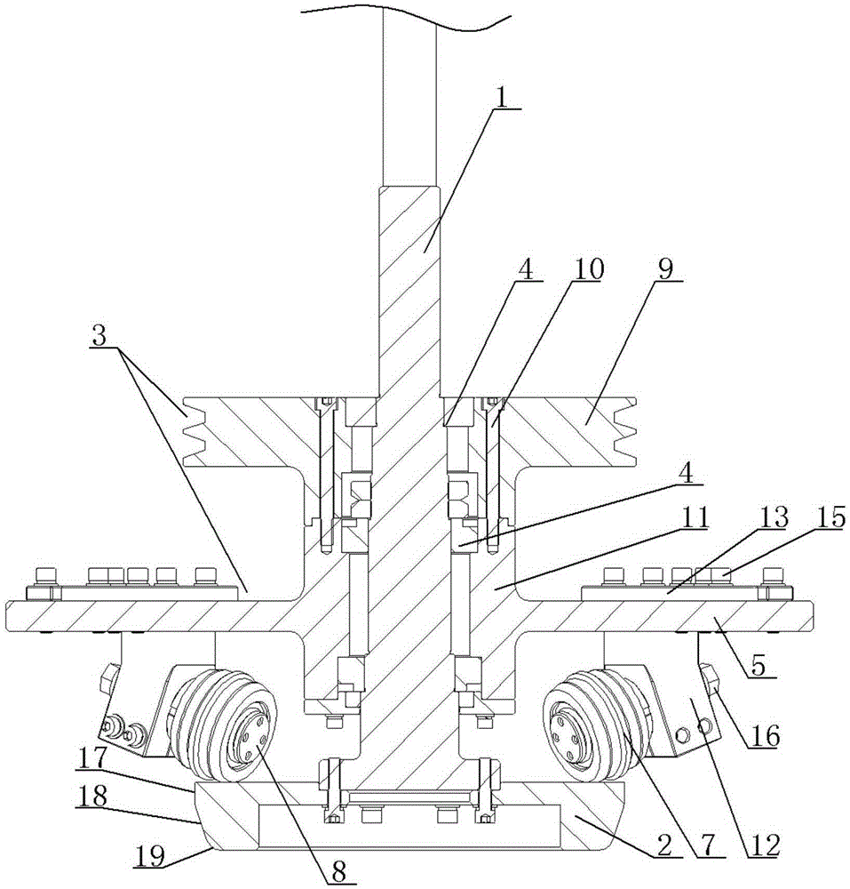
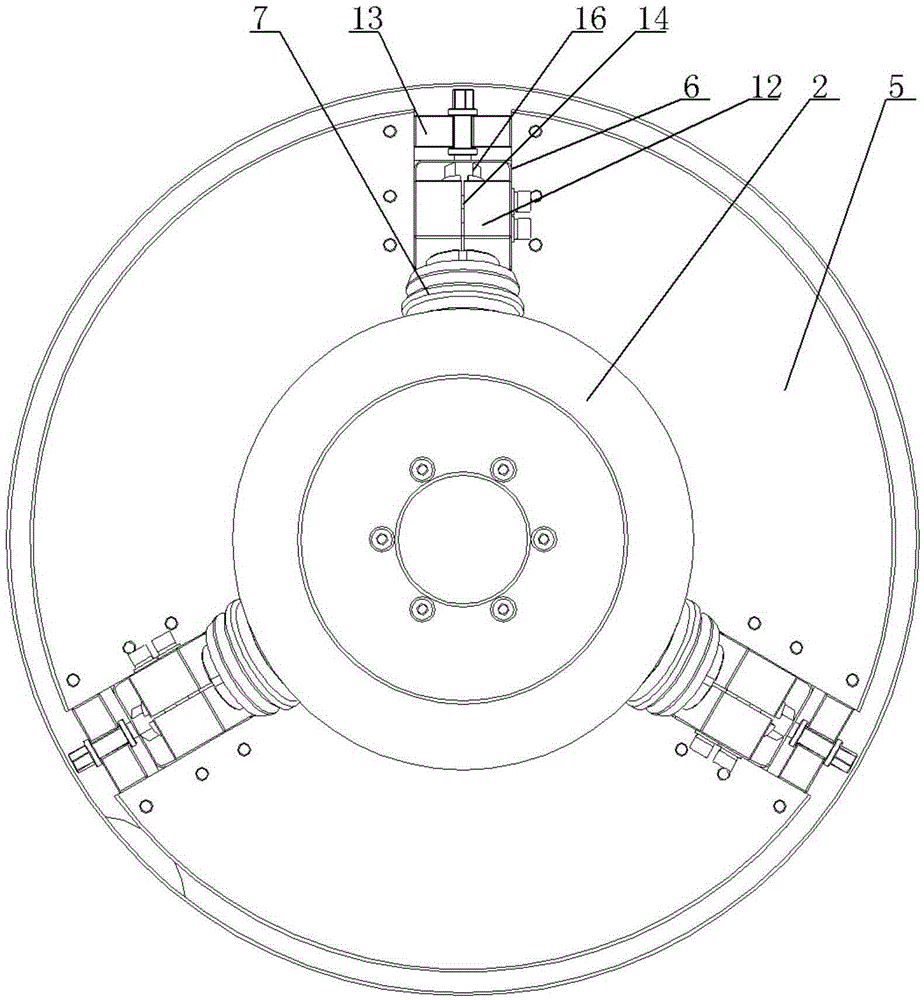
[0015] A crimping mechanism, see figure 1 , figure 2 : It includes a central shaft 1, the lower end of the central shaft 1 is fastened with a positioning disc 2, the middle position of the central shaft 1 is covered with a rotating seat 3, the rotating seat 3 and the central shaft 1 are arranged with a bearing structure 4, and the upper part of the rotating seat 3 Specifically for the transmission mechanism, the lower part of the swivel seat 3 is a flange structure 5, and the circular surface of the flange structure 5 is evenly distributed with the winding roller installation groove 6 with its center as the center of the circle, and the winding roller installation groove 6 is along the flange structure 5. The radial arrangement of the circular surface, the winding roller 7 is arranged below the corresponding winding roller installation groove 6, the winding roller 7 is positioned in the winding roller installation groove 6 through the fastening structure, and the rotating sha...


PUM


Abstract

The invention discloses a crimping mechanism. Through rotation parallel to a barrel opening, the edges of materials are crimped when idler wheels rotate and a barrel body is slowly lifted. The cutting edge face of the barrel body of the crimping mechanism is directly coated with the crimped edges, openings of the crimping edges are smooth, a crimping portion of a barrel can not be abraded in the crimping process, and crimping quality is guaranteed. The crimping mechanism comprises a center shaft and is characterized in that a locating disc is fastened to the lower end of the center shaft, the middle position of the center shaft is sleeved with a rotary base, a bearing structure is arranged on the rotary base and the center shaft, the upper portion of the rotary base is specifically provided with a transmission mechanism, the lower portion of the rotary base is of a flange structure, crimping line idler wheel installation grooves are evenly distributed in the circular face of the flange structure and with the center of the circular face serving as the center of a circle, the crimping line idler wheel installation grooves are formed in the radial direction of the circular face of the flange structure, the crimping line idler wheels are arranged below the corresponding crimping line idler wheel installation grooves, and the crimping line idler wheels are located in the crimping line idler wheel installation grooves through fastening structures.

Description

technical field [0001] The invention relates to the technical field of convenient bucket making equipment, in particular to a crimping mechanism. Background technique [0002] In the production of convenient barrels, the barrel body needs to be crimped at the position of the barrel mouth after the mouth is expanded. At present, the method of crimping the upper barrel mouth of the convenient barrels in the industry: use the crimping die to apply pressure perpendicular to the barrel body , and then achieve the curling effect of the mold size design. Since the groove of the curling mold is in full contact with the curling part of the convenience bucket, it wears a lot on the curling mold and is easy to damage the curling part of the convenience bucket. The paint is rubbed off, and the size and shape of the curling cannot be adjusted. Contents of the invention [0003] In view of the above problems, the present invention provides a crimping mechanism, which uses the rotation ...

Claims


Application Information

Patent Timeline
Patent Type & Authority Patents(China)
IPC IPC(8): B21D19/12
Inventor 程立斌黄小林孔桢焕徐民兴
Owner SUZHOU HYCAN HLDG CO LTD
Why Eureka
Try Eureka