Scraper conveyer and fully-mechanized coal mining device

A technology of scraper conveyor and scraper, which is applied in the field of scraper conveyor and fully mechanized mining equipment, and can solve left-right deflection (horizontal deflection) or up-and-down deflection (vertical deflection, shearer traction gear tooth meshing) Avoid problems such as wear and large changes in the meshing pitch of the pin teeth, so as to achieve the effects of not easily causing failures, smooth traction and cutting, and reducing meshing wear

Active Publication Date: 2014-10-29
SANY HEAVY EQUIP
View PDF6 Cites 2 Cited by
  • Summary
  • Abstract
  • Description
  • Claims
  • Application Information

AI Technical Summary

Problems solved by technology

Because the contact surface between the shearer and the coal seam (also known as the working surface) has fluctuations, and the ground laid by the scraper conveyor is not completely flat, the shearer is cutting the coal seam, especially when walking to the adjacent two When the butt joint of the grooves in the middle of the joints, it will cause relative left and right deflection (deflection in the horizontal direction) or deflection in the vertical direction (deflection in the vertical direction) between the two adjacent middle grooves, and a gap will be generated, resulting in the gap between the two adjacent middle grooves. The pin tooth pitch between the grooves varies greatly, resulting in severe meshing wear of the traction gear teeth of the coal mining machine
[0005] At present, in order to ensure the pin-tooth meshing pitch between the middle grooves of two adjacent sections, the end faces of the sides of the baffle plates or the sides of the blades facing each other in the middle grooves of the adjacent two sections are in close contact with each other. The end face of the groove side of the baffle plate or the end face of the groove side of the shovel plate provides a technical solution for the relative rotation between the two adjacent middle grooves. Big situation, but the improvement effect is not obvious

Method used


Image

  • Scraper conveyer and fully-mechanized coal mining device
  • Scraper conveyer and fully-mechanized coal mining device
  • Scraper conveyer and fully-mechanized coal mining device

Examples


Embodiment Construction

[0029] It should be noted that, in the case of no conflict, the embodiments in the present application and the features in the embodiments can be combined with each other. The present invention will be described in detail below with reference to the accompanying drawings and examples.

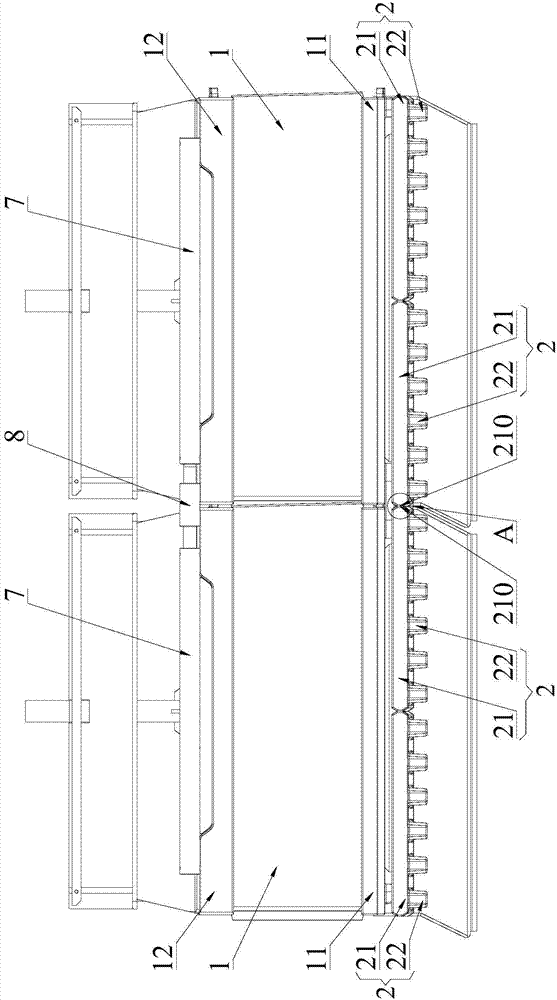
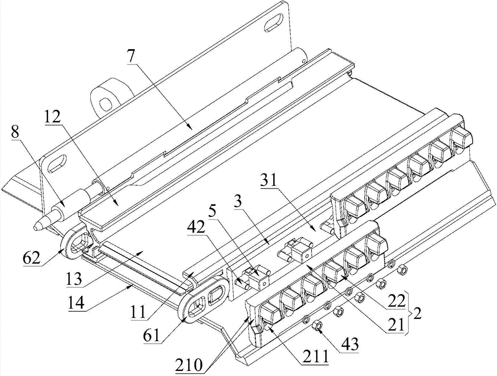
[0030] see figure 1 , shows the top view structure of the middle trough 1 with two adjacent sections in the scraper conveyor provided by the embodiment of the present invention. Those skilled in the art can understand that when working in the roadway, the scraper conveyor usually includes multiple sections sequentially The connected middle groove 1 provides a longer walking track for the shearer.

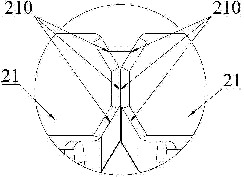
[0031] combined reference Figure 3 to Figure 7 Each middle groove 1 includes a baffle groove side 12, a middle plate 13, a bottom plate 14 and a blade groove side 11, and the middle plate 13 and the bottom plate 14 are respectively connected between the baffle groove side 12 and the blade groove s...


PUM


Abstract

The invention provides a scraper conveyer and a fully-mechanized coal mining device. The scraper conveyer comprises at least two middle troughs, and the outer side of a shoveling plate ledge of each middle trough is provided with pin rails used for being matched with traveling gear teeth of a coal mining machine. Each pin rail comprises pin teeth and a pin tooth base located between the corresponding pin teeth and the corresponding shoveling plate ledge. The opposite end faces of the corresponding pin tooth bases of two adjacent middle troughs make contact with each other, and a rotation center is provided for relative rotation between two adjacent middle troughs through the end faces, making contact with each other, of the corresponding pin tooth base. The scraper conveyer can effectively improve the situation that the meshing pitch of the pin teeth of two adjacent middle troughs changes greatly, and the service life of the pin rails and the service life of the traveling gear teeth of the coal mining machine are prolonged.

Description

technical field [0001] The present invention relates to mining conveying equipment, more specifically, to a scraper conveyor and fully mechanized mining equipment. Background technique [0002] According to the coal seam thickness division of coal mines in my country, the coal seam with a thickness of 0.8m-1.3m is a thin coal seam, and the coal seam with a thickness below 0.8m is an extremely thin coal seam. Thin coal seams and extremely thin coal seams are difficult-to-mining coal seams. and production efficiency, the design of fully mechanized mining equipment with a low machine face height and a large coal throughput has become the key to solving the mining problem of difficult coal seams. [0003] Fully mechanized mining equipment includes scraper conveyor and coal shearer. The scraper conveyor includes multiple middle troughs that are sequentially connected by connecting rings. and the bottom plate are respectively connected between the side of the baffle plate and the ...

Claims


Application Information

Patent Timeline
Patent Type & Authority Applications(China)
IPC IPC(8): B65G21/22
Inventor 鞠鹏科诺尔张彦国
Owner SANY HEAVY EQUIP
Why Eureka
Try Eureka