Electrooptical modulator

A technology of electro-optic modulator and electrode, which is applied in the direction of instruments, optics, nonlinear optics, etc., and can solve problems such as the decrease of extinction ratio

Inactive Publication Date: 2014-10-29
HONG FU JIN PRECISION IND (SHENZHEN) CO LTD +1
View PDF5 Cites 1 Cited by
  • Summary
  • Abstract
  • Description
  • Claims
  • Application Information

AI Technical Summary

Problems solved by technology

However, the power of the light beams transmitted in the two branches of the Y-shaped optical waveguide often has a small difference, resulting in that when the electro-optic modulato...

Method used


Image

  • Electrooptical modulator
  • Electrooptical modulator

Examples


Embodiment Construction

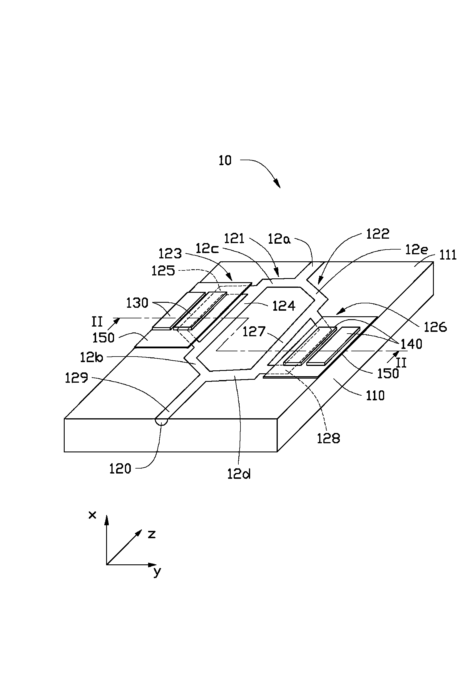
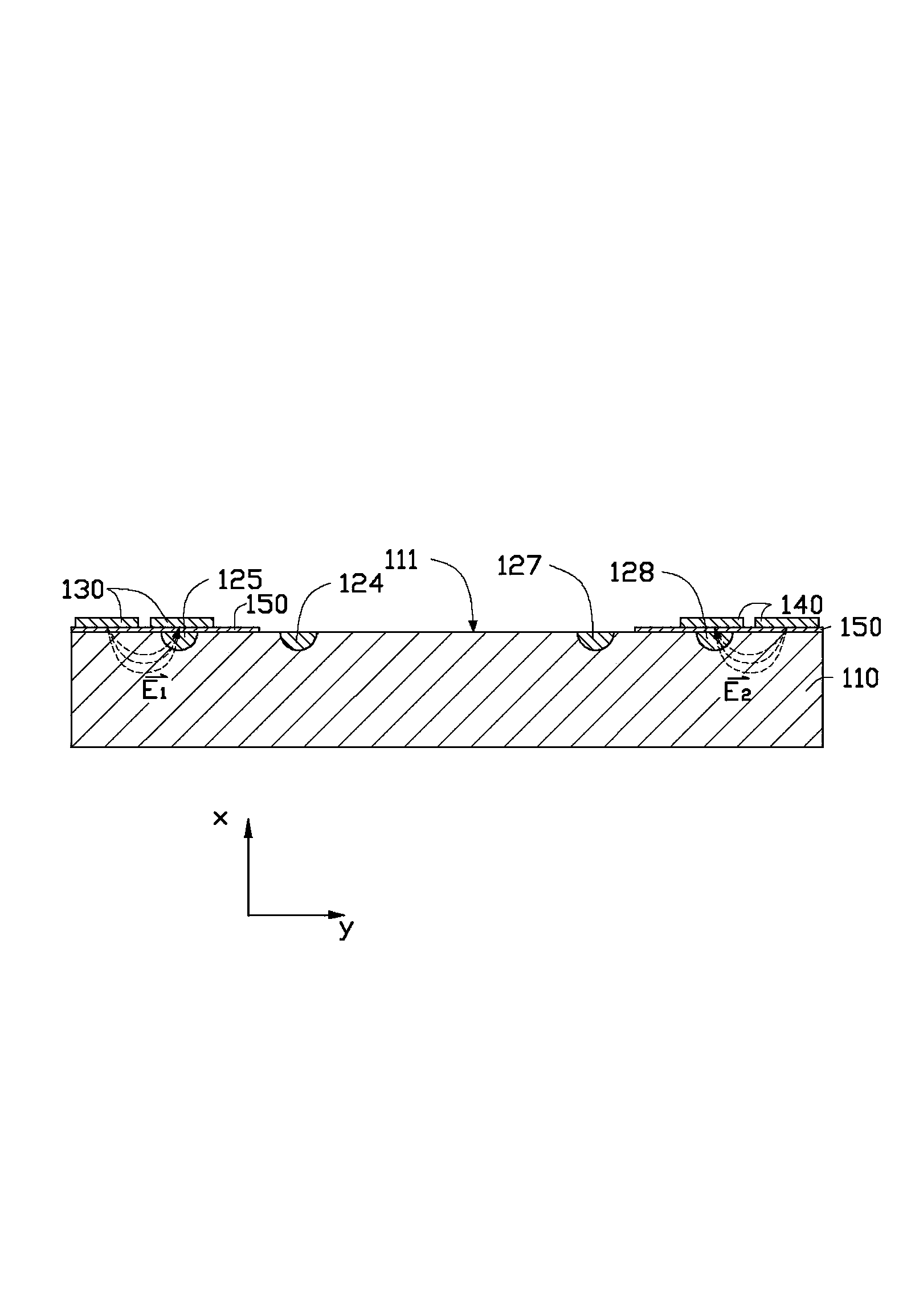
[0016] See figure 1 and figure 2 The electro-optical modulator 10 of the preferred embodiment of the present invention includes a substrate 110, a Y-shaped optical waveguide 120, a first electrode 130, and a second electrode 140. The Y-shaped optical waveguide 120 is formed on the substrate 110 and includes a first branch 121 and a second branch 122. The first branch 121 includes a first sub-Y-type optical waveguide 123, the first sub-Y-type optical waveguide 123 includes a first sub-branch 124 and a second sub-branch 125, and the second branch 122 includes a second sub-branch The Y-shaped optical waveguide 126 includes a third sub-branch 127 and a fourth sub-branch 128. The second sub-branch 125 and the fourth sub-branch 128 are located on both sides of the first sub-branch 124 and the third sub-branch 127 respectively. The pair of first electrodes 130 are disposed on the substrate 110, and respectively cover the second sub-branch 125 and parallel to the second sub-branch 12...


PUM


Abstract

The invention provides an electrooptical modulator which comprises a base, a Y-type optical waveguide formed on the substrate, a pair of first electrodes arranged on the base and a pair of second electrodes arranged on the substrate. The Y-type optical waveguide comprises a first branch and a second branch, the first branch comprises a first sub-Y-type optical waveguide, the first sub-Y-type optical waveguide comprises a first sub-branch and a second sub-branch, the second branch comprises a second sub-Y-type optical waveguide, and the second sub-Y-type optical waveguide comprises a third sub-branch and a fourth sub-branch. The pair of the first electrodes and the pair of the second electrodes are used for modulating the first sub-Y-type optical waveguide and the second sub-Y-type optical waveguide respectively to enable the light beam output by the first sub-Y-type optical waveguide and the light beam output by the second sub-Y-type optical waveguide to output to be identical in power, and therefore the extinction ratio is increased.

Description

Technical field [0001] The invention relates to a high-speed optical communication system, in particular to an electro-optical modulator. Background technique [0002] The Mach-Zehner electro-optic modulator uses the electro-optic effect to change the equivalent refractive index of one of the two branches of the Y-shaped optical waveguide by modulating the electric field, thereby changing the phase of the light beam propagating in it to make it comparable to the Y-shaped light. The light beam propagating in the other branch of the waveguide has a phase difference. In this way, the light beams transmitted in the two branches of the Y-shaped optical waveguide will interfere after re-convergence, and the output power depends on the phase difference, that is, is determined by the modulating electric field, thereby achieving modulation. However, the power of the light beams transmitted in the two branches of the Y-shaped optical waveguide is often slightly different, resulting in tha...

Claims


Application Information

Patent Timeline
IPC IPC(8): G02F1/225
Inventor 黄新舜
Owner HONG FU JIN PRECISION IND (SHENZHEN) CO LTD
Why Eureka
Try Eureka