Electro-optical modulator

An electro-optic modulator and modulation electrode technology, applied in the field of integrated optics, can solve problems such as the decrease of extinction ratio, and achieve the effects of improved extinction ratio, less coupling, and less transmission.

Inactive Publication Date: 2014-12-24
HONG FU JIN PRECISION IND (SHENZHEN) CO LTD +1
View PDF5 Cites 1 Cited by
  • Summary
  • Abstract
  • Description
  • Claims
  • Application Information

AI Technical Summary

Problems solved by technology

However, there is often a slight difference in the power of the beams transmitted in the two branches of the Y-shaped planar optical waveguide, resulting in that when the electro-optic modulator is used as a switch, there is still a small power output in the off state, but the output power is not the maximum in the on state, and the extinction ratio (extinction ratio) down

Method used


Image

  • Electro-optical modulator
  • Electro-optical modulator
  • Electro-optical modulator

Examples


Embodiment Construction

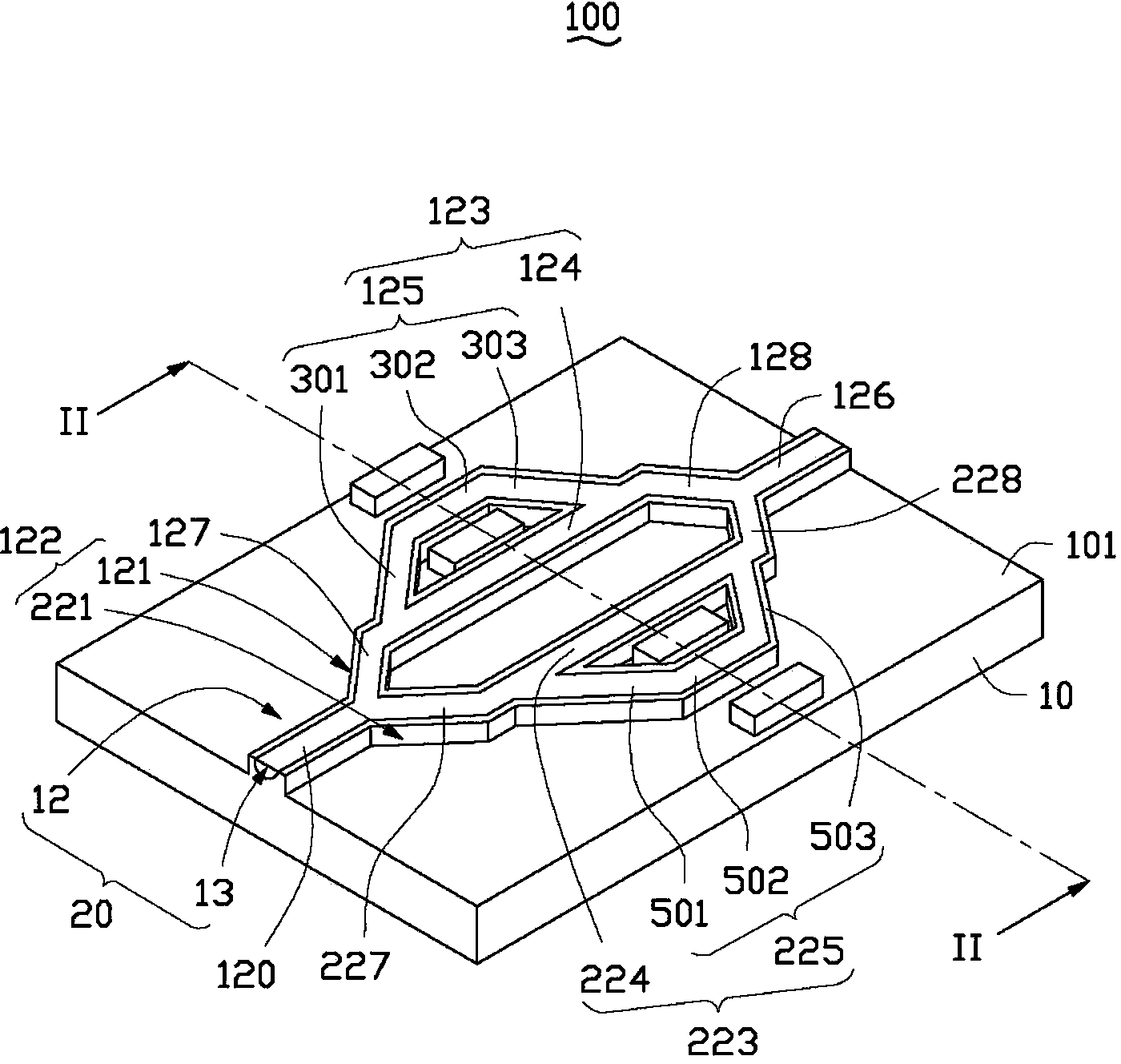
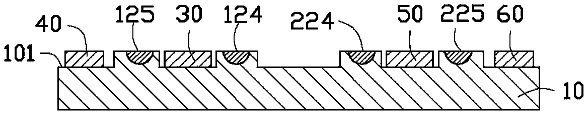
[0015] see Figure 1-2 , an electro-optic modulator 100 provided in a preferred embodiment of the present invention, which includes: a substrate 10, a ridge-shaped optical waveguide structure 20, a first ground electrode 30, a first modulation electrode 40, a second ground electrode 50 and a second modulation electrode 60.

[0016] The substrate 10 includes a top surface 101 on which the ridge optical waveguide structure 20 is located. The ridge optical waveguide structure 20 includes a ridge structure 12 formed on the top surface 101 and a ridge structure 12 formed in The optical waveguide 13. The material of the substrate 10 is lithium niobate crystal or barium niobate crystal. The material of the optical waveguide 13 is titanium, nickel, zinc, gallium or zinc-nickel alloy. The width of the optical waveguide 13 is smaller than the width of the ridge structure 12 . In this embodiment, the height of the substrate 10 is 3mm, and the height of the ridge structure is between ...


PUM

PropertyMeasurementUnit
heightaaaaaaaaaa

Abstract

The invention relates to an electro-optical modulator which comprises a base, a ridge-shaped optical waveguide structure, a first ground electrode, a first modulation electrode, a second ground electrode and a second modulation electrode. The ridge-shaped optical waveguide structure is located at the top surface of the base and comprises a ridge-shaped structure and an optical waveguide formed in the ridge-shaped structure; the ridge-shaped structure comprises a Y-shaped fork part; the fork part comprises a first branch and a second branch; the first branch comprises a first sub-Y-shaped optical waveguide and comprises a first sub-branch and a second sub-branch; the second branch comprises a second sub-Y-shaped optical waveguide and comprises a third sub-branch and a fourth sub-branch; both the first ground electrode and the first modulation electrode are used for modulating the first sub-Y-shaped optical waveguide; both the second ground electrode and the second modulation electrode are used for modulating the second sub-Y-shaped optical waveguide. Therefore, the first sub-Y-shaped optical waveguide and the second sub-Y-shaped optical waveguide output the same power, and the extinction ratio is accordingly improved.

Description

technical field [0001] The invention relates to integrated optics, in particular to an electro-optic modulator. Background technique [0002] The Mach-Zehner electro-optic modulator uses the electro-optic effect to change the equivalent refractive index of one of the two branches of the Y-shaped optical waveguide by modulating the electric field, thereby changing the phase of the beam transmitted in it, making it consistent with the Y-shaped optical waveguide. There is a phase difference between the beams propagating in the other branch of the waveguide. In this way, the light beams transmitted in the two branches of the Y-shaped optical waveguide will interfere after being recombined, and the output power depends on the phase difference, that is, it is determined by the modulation electric field, so as to realize modulation. However, there is often a slight difference in the power of the beams transmitted in the two branches of the Y-shaped planar optical waveguide, result...

Claims


Application Information

Patent Timeline
Patent Type & Authority Applications(China)
IPC IPC(8): G02F1/035
Inventor 黄新舜
Owner HONG FU JIN PRECISION IND (SHENZHEN) CO LTD
Why Eureka
Try Eureka