Connector

A technology of connectors and terminals, applied in the field of connectors, can solve the problems of not being able to fully ensure positional accuracy and holding force, and not being able to hold the housing 525, and achieve the effects of precise positioning and holding, and high sealing characteristics

Inactive Publication Date: 2014-10-29
YAZAKI CORP
View PDF5 Cites 3 Cited by
  • Summary
  • Abstract
  • Description
  • Claims
  • Application Information

AI Technical Summary

Problems solved by technology

Therefore, this side cannot be held directly by the housing 525
This leads to a problem that positional accuracy and holding force cannot be sufficiently ensured within the terminal 527

Method used


Image

  • Connector
  • Connector
  • Connector

Examples


Embodiment Construction

[0035] Embodiments of the present invention are described below with reference to the drawings.

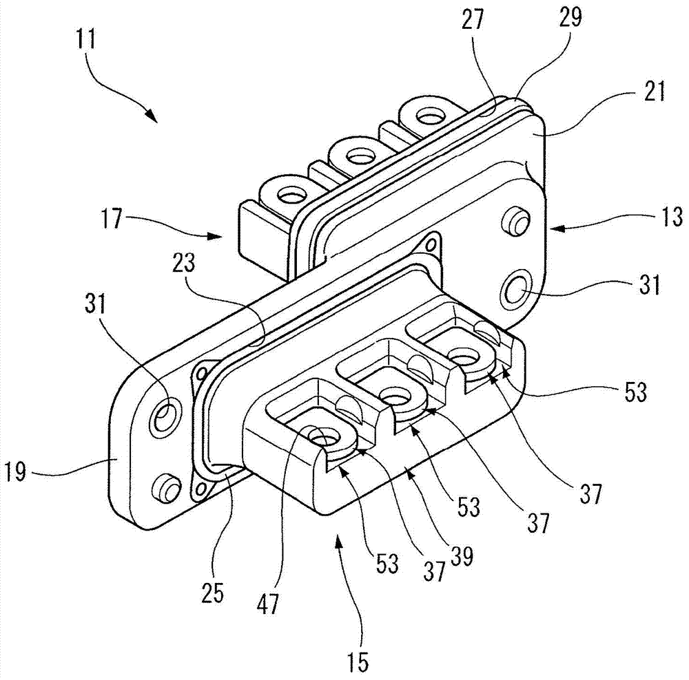
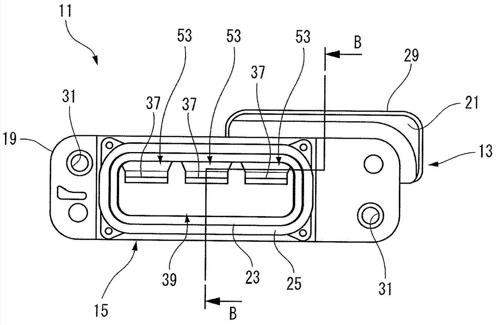
[0036] Such as figure 1 As shown, the connector 11 according to the embodiment of the present invention is mounted to a motor side panel (not shown) and an inverter side panel (not shown).

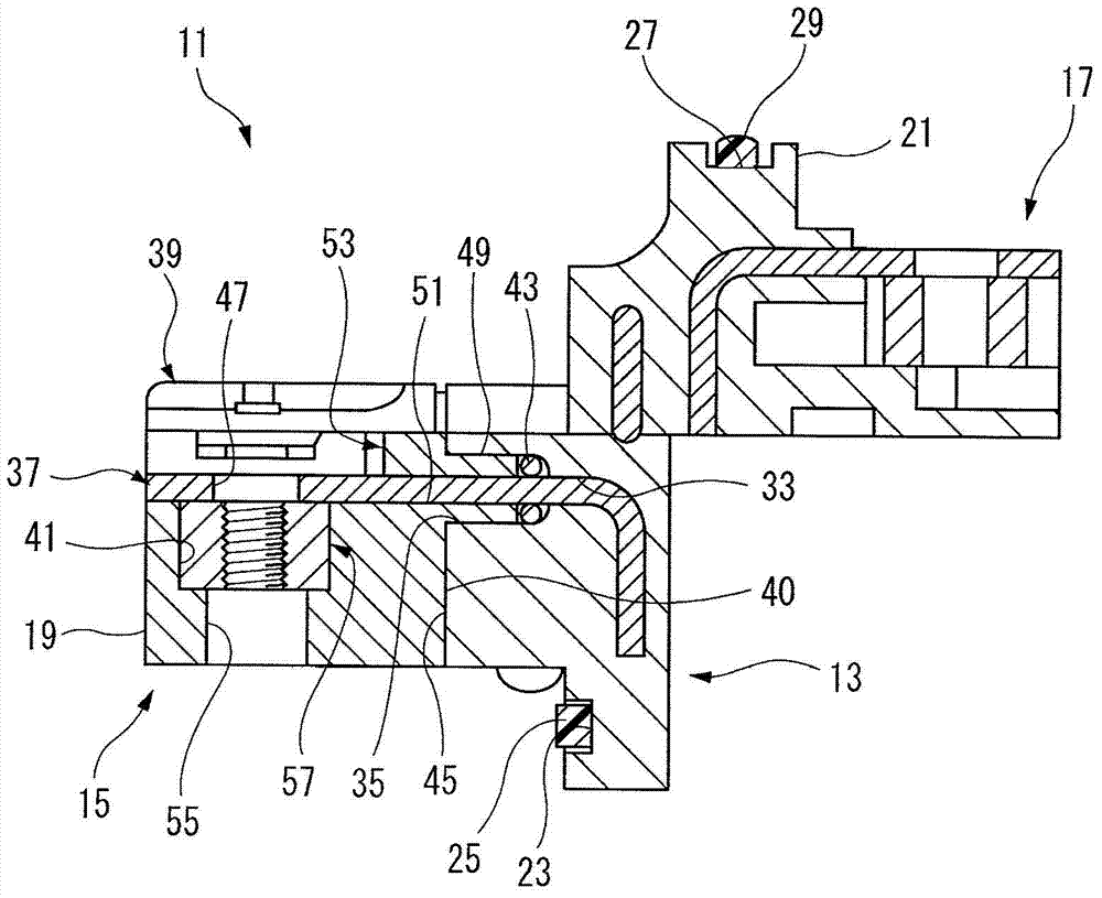
[0037] The connector 11 includes a housing 13 (also referred to as a terminal block) formed of a synthetic resin having insulating properties. The housing 13 is provided with a motor-side connecting portion 15 on the mounting side mounted to the motor-side panel. The housing 13 is provided with an inverter-side connecting portion 17 on the mounting side mounted to the inverter-side panel.

[0038]Inside the housing 13, a motor-side flange 19 and an inverter-side flange 21 are formed parallel to each other. The motor side flange 19 and the inverter side flange 21 are attached to a motor side mounting hole (not shown) formed in the panel on the motor side and an inverter mounting hole formed...


PUM


Abstract

A connector includes a housing, a terminal, a seal holder and fastening piece. The terminal is inserted into a terminal passing hole and a seal mounting hole of the housing and passes through an annular seal member. The terminal has a protruding tip part having a fastening hole and protruding from an outer surface of the housing. The seal holder includes a press fitting protrusion that is fit into the seal mounting hole and thereby pushes in and positions the annular seal member, a terminal leading hole that leads the terminal inserted into the press fitting protrusion, and an engagement recess that is formed at a leading end side of the terminal leading hole and is opened in a direction perpendicular to the leading direction of the terminal leading hole.

Description

technical field [0001] The present invention relates to a connector having a structure to prevent liquids such as water and oil from flowing into a housing. Background technique [0002] For example, in electric vehicles, there is known a connector (terminal block) for electrically connecting an inverter and a motor to each other. [0003] exist Figures 7A to 7C In the terminal block 501 shown in , bus bars 503 serving as terminals are connected to each contact element (not shown) of the motor and inverter with nuts and bolts (fasteners) and then energized. The bus bar 503 is held in such a manner as to pass through the housing 505 . Inside the housing 505, a motor-side flange 507 and an inverter-side flange 509 are formed parallel to each other. The motor side flange 507 and the inverter side flange 509 are respectively attached to the motor side mounting hole formed in the panel on the motor side and the inverter side mounting hole formed in the panel on the inverter si...

Claims


Application Information

Patent Timeline
IPC IPC(8): H01R13/52H01R13/02H01R13/639H01R13/46H01R13/40
CPCH01R13/5205H01R2105/00H01R13/521H01R13/5219H01R13/4223
Inventor 冈本健一长泽聪之
Owner YAZAKI CORP
Why Eureka
Try Eureka