
Power circuit

A circuit and power module technology, applied in the electronic field, can solve the problems of large circuit loss and heat generation, complex circuit structure, and inconvenient switching, and achieve the effect of convenient automatic switching, simple circuit structure, and avoiding loss and heat generation

Active Publication Date: 2014-11-05
SHENZHEN OCEANS KING LIGHTING ENG CO LTD +1
View PDF6 Cites 3 Cited by
  • Summary
  • Abstract
  • Description
  • Claims
  • Application Information

AI Technical Summary

Problems solved by technology

However, in the prior art, these two power supply circuits generally exist and work separately. If the load current of the circuit is small, a linear regulated power supply can be used, but when the load is heavy, the linear regulated power supply can continue to be used. Otherwise, the loss and heat generation of the circuit will be large, so it is necessary to switch to the switching power supply when the load current is high to reduce the loss and heat generation of the circuit. In this case, two power supply circuits need to be independently set in the circuit and manually selected Switching, complex circuit structure, high cost, and inconvenient switching

Method used


Image

  • Power circuit
  • Power circuit

Examples


Embodiment Construction

[0022] The following will clearly and completely describe the technical solutions in the embodiments of the present invention with reference to the accompanying drawings in the embodiments of the present invention. Obviously, the described embodiments are only some, not all, embodiments of the present invention. Based on the embodiments of the present invention, all other embodiments obtained by persons of ordinary skill in the art without creative efforts fall within the protection scope of the present invention.

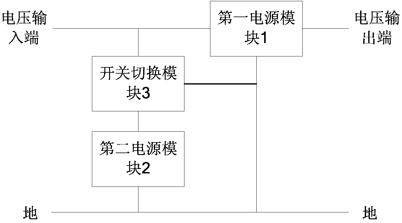
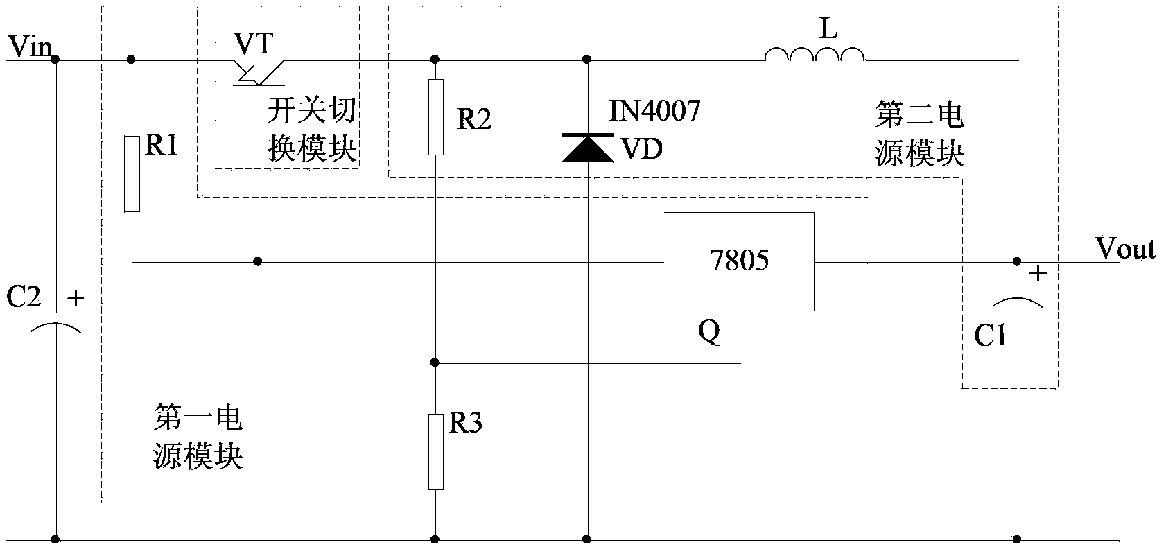
[0023] Please refer to figure 1 , is a connection schematic diagram of the first embodiment of the power circuit of the present invention. In this embodiment, the circuit includes: a first power module 1 , a second power module 2 , and a switch module 3 .

[0024] The first power module 1 is respectively connected to the voltage input terminal, the voltage output terminal and the ground, and is used to output the load current when the load current is less than the ...


PUM


Abstract

The embodiment of the invention discloses a power circuit which comprises a first power module, a second power module and a switch switching module, wherein the first power module is connected with a voltage input end, a voltage output end and ground and used for outputting a load current when the load current is lower than a preset current; the second power module is connected between the voltage input end and the ground and used for outputting the load current when the load current reaches the preset current; and the switch switching module is connected with the voltage input end, the first power module and the second power module and used for switching to the second power module so as to output the load current when the load current reaches the preset current. With the adoption of the power circuit, the power circuit can be automatically switched according to the size of the load current, stable working of a load is kept, and the power circuit is simple in structure and low in cost.

Description

technical field [0001] The invention relates to the field of electronics, in particular to a power supply circuit. Background technique [0002] In the field of electronic circuits, power circuits are widely used as the working basis of other circuits. In particular, switching power supply and linear regulated power supply are the most common and most frequently used power supply circuits, and their role cannot be ignored. However, in the prior art, these two power supply circuits generally exist and work separately. If the load current of the circuit is small, a linear regulated power supply can be used, but when the load is heavy, the linear regulated power supply can continue to be used. Otherwise, the loss and heat generation of the circuit will be large, so it is necessary to switch to the switching power supply when the load current is high to reduce the loss and heat generation of the circuit. In this case, two power supply circuits need to be independently set in th...

Claims


Application Information

Patent Timeline
Patent Type & Authority Applications(China)
IPC IPC(8): H02M3/06H02M3/07
Inventor 周明杰屈煜
Owner SHENZHEN OCEANS KING LIGHTING ENG CO LTD
Learn More