Touch switch and operation panel

A technology of touch switch and operation panel, which is applied in the field of capacitive touch switch and operation panel, which can solve the problems of cost increase, wrong judgment of touch operation, increase in the number of parts, etc., and achieve the effect of reducing danger

Active Publication Date: 2018-07-06
U SHIN LTD
View PDF7 Cites 0 Cited by
  • Summary
  • Abstract
  • Description
  • Claims
  • Application Information

AI Technical Summary

Problems solved by technology

In addition, in such a structure, if the brightness of the light-emitting diode is adjusted by PWM control, the fluctuation of the capacitance of the electrode due to the noise generated by it will increase, and there is a possibility of erroneous judgment of the touch operation.
[0015] According to the method of arranging the light-emitting diodes separately from the electrodes or the method of adjusting the brightness by controlling the amount of current of the light-emitting diodes, the above-mentioned influence of the noise can be reduced, but any method increases the number of parts, thereby leading to an increase in cost

Method used


Image

  • Touch switch and operation panel
  • Touch switch and operation panel
  • Touch switch and operation panel

Examples


no. 1 approach

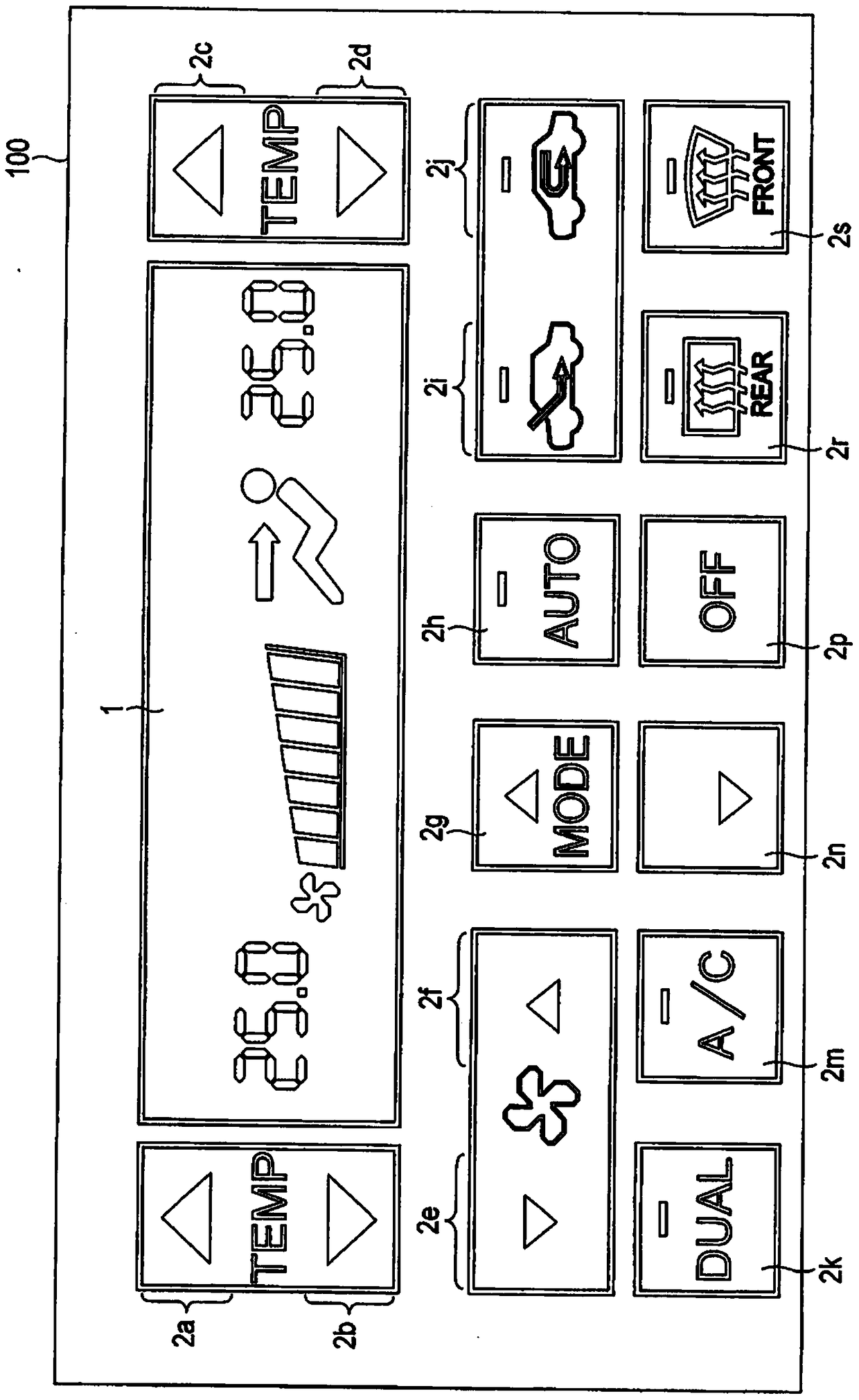
[0036] figure 1 is a plan view showing the appearance of the operation surface of the operation panel 100 according to the first embodiment.

[0037] The operation panel 100 is exposed to the outside of the operation surface, and includes the display device 1 and the operation parts 2a, 2b, 2c, 2d, 2e, 2f, 2g, 2h, 2i, 2j, 2k, 2m, 2n, 2p, 2r. , 2s.

[0038] The display device 1 is, for example, a liquid crystal display device, and displays an image showing an operating state of an air conditioner of a vehicle.

[0039] The operation parts 2 a to 2 s are parts on the operation surface that must be touched by the operator. A part of the operation parts 2a to 2s is formed of characters or symbols using a light-transmitting material, and the other part is formed of a light-shielding material.

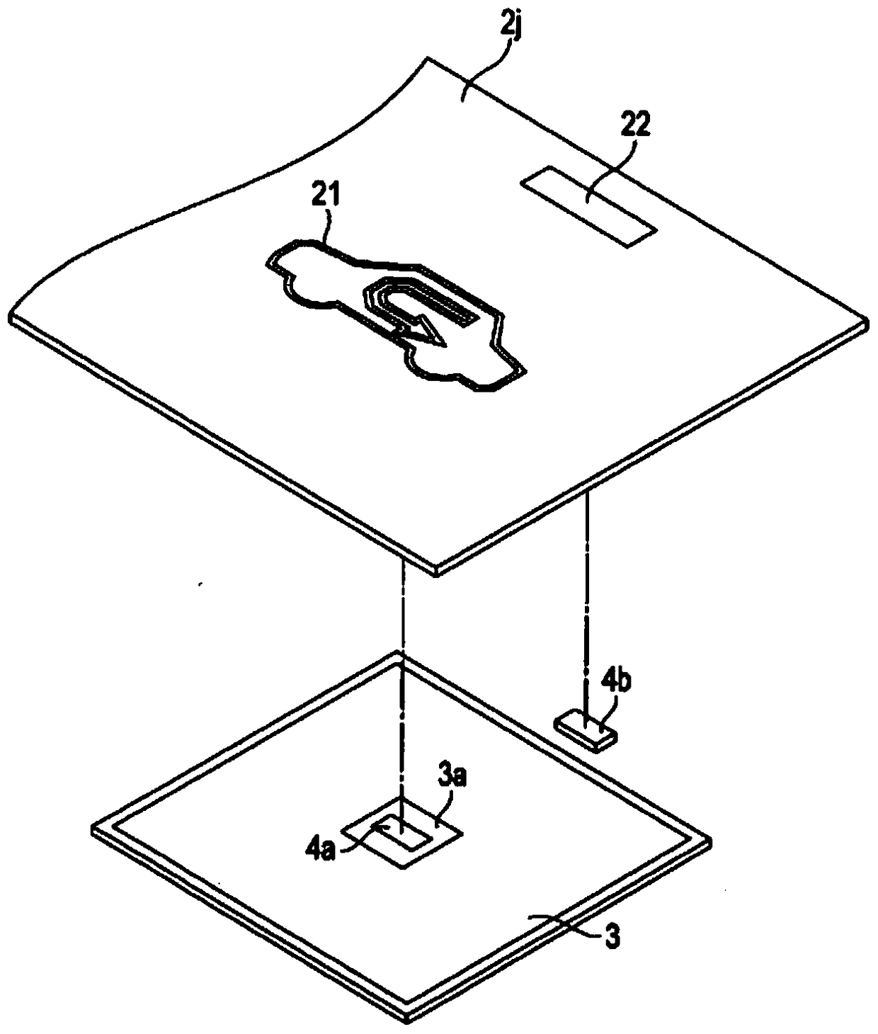
[0040] One electrode and at least one light emitting diode are arranged inside the operation panel 100 so as to face each of the operation parts 2a to 2s.

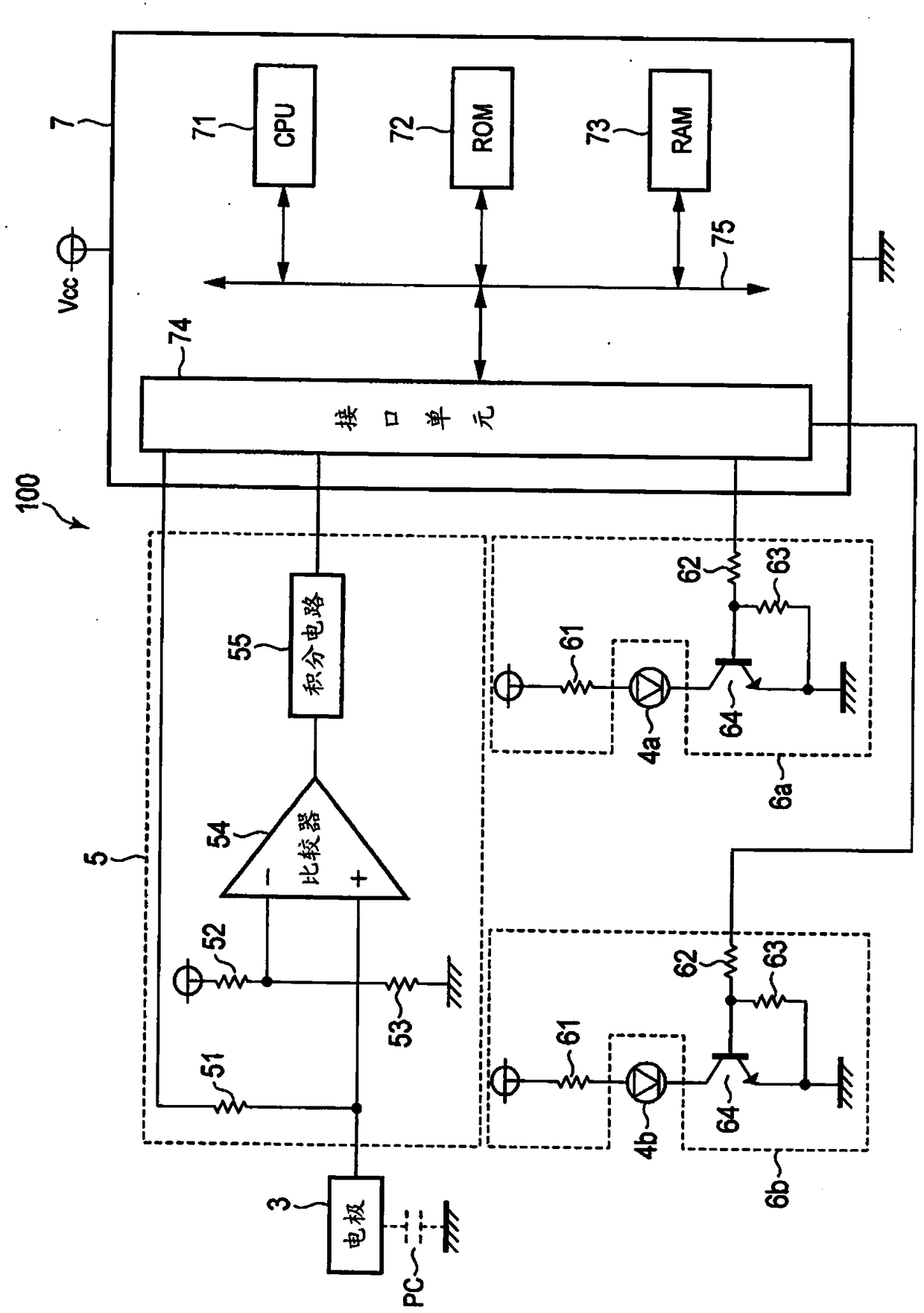
[0041] figure 2 It is an e...

no. 2 approach

[0121] figure 2The shown structure is an example using the self-capacitance method, but the above-described embodiments can be used almost directly even if the mutual-capacitance method is used.

[0122] Figure 7 It is a plan view showing the electrode structure of one touch switch in the second embodiment. But when Figure 7 For and figure 2 Like elements are shown with the same symbols. And the detailed description thereof is omitted.

[0123] like Figure 7 As shown, when the mutual capacitance method is adopted, a touch switch includes multiple receiving electrodes 31 and at least one transmitting electrode 32 . But when Figure 7 A state in which four reception electrodes 31 and one transmission electrode 32 are provided is shown.

[0124] Figure 8 is a schematic diagram showing the electrical component part of the operation panel 200 according to the second embodiment. But when Figure 8 For and figure 2 Like elements are shown with the same symbols. An...


PUM


Abstract

A technique reduces erroneous judgment due to effects of noise accompanying PWM control while using PWM control for brightness adjustment of light-emitting diodes disposed proximate of an electrode. An electrode is disposed proximate of operating portions that are subject to touch operations by unit of a conductive body. An operating portion of a light-emitting diode is lightened. A CPU performs brightness adjustment of the light-emitting diode through PWM control. A detecting circuit outputs detected values in accordance with electrostatic capacitances of the electrode. The CPU judges that a touch operation has been made when a difference between a detected value of the detecting circuit and a reference value stored in a RAM is not less than a prescribed value. The CPU stores a detected value that is first detected by the detecting circuit after transition of an executing state of PWM control in the RAM as a reference value.

Description

technical field [0001] The present invention relates to a capacitive touch switch that detects a touch operation of a conductor such as a human body through a change in capacitance, and an operation panel including a plurality of the touch switch. Background technique [0002] The operation panel used for the operation of the air conditioner of the vehicle is equipped with light-emitting diodes so that the characters and symbols explaining the functions of the switches can be seen clearly, and the operation status of the switches can be displayed. A brightness adjustment function for reducing the brightness of the LEDs at night is currently disclosed. In addition, in order to realize the brightness adjustment function, low-cost PWM (pulse width modulation: pulse width modulation) control with a small number of components is generally used. [0003] However, capacitive touch switches are currently widely used because a simple design without unevenness can be realized and the...

Claims


Application Information

Patent Timeline
Patent Type & Authority Patents(China)
IPC IPC(8): H03K17/96
CPCH03K17/962H03K2217/96073
Inventor 土肥泉福岛一幸
Owner U SHIN LTD
Why Eureka
Try Eureka