

Voltage detection circuit and electronic circuit
A technology of voltage detection circuit and circuit, which is applied in the direction of electronic switches, electrical components, pulse technology, etc., can solve the problems of false activation of enable signal, inability to achieve small area, low consumption current, and slow reference voltage, etc., to prevent The effect of misuse
- Summary
- Abstract
- Description
- Claims
- Application Information
AI Technical Summary
Problems solved by technology
Method used
Image

Examples
no. 1 Embodiment approach 》
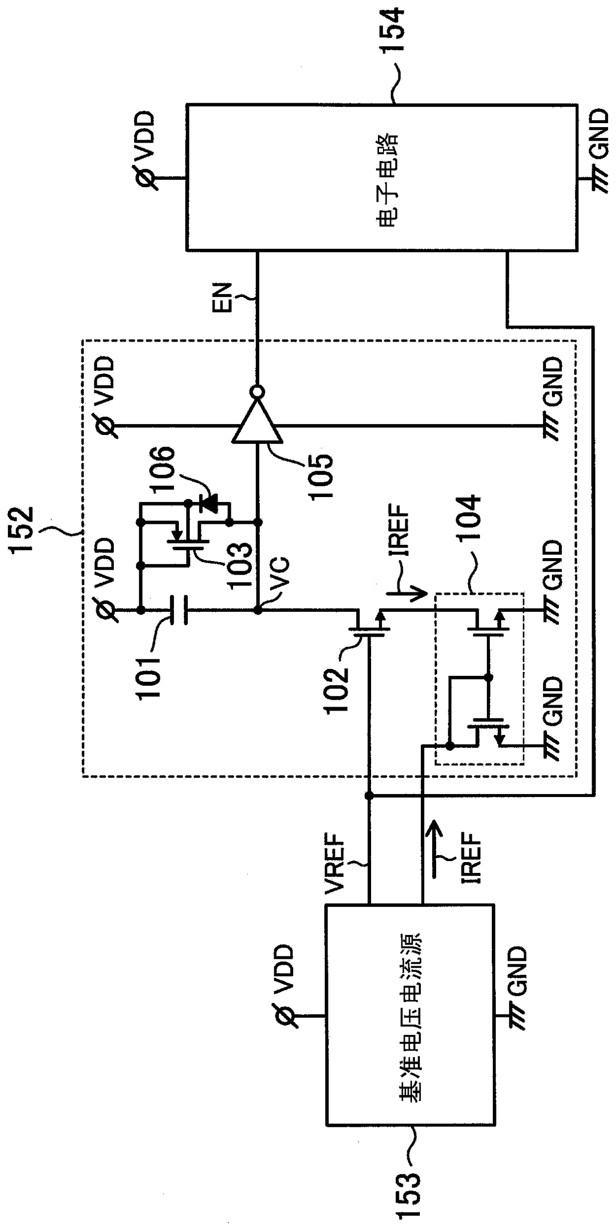
[0024] figure 1 It is a circuit diagram including the voltage detection circuit according to the first embodiment of the present invention. The voltage detection circuit according to the first embodiment includes an enable signal output circuit 152 and a reference voltage current source 153, and supplies the reference voltage VREF and the enable signal EN to the electronic circuit 154. The electronic circuit 154 is connected to the power supply voltage VDD and the ground voltage GND, and receives the reference voltage VREF from the reference voltage current source 153 and the enable signal EN from the enable signal output circuit 152, respectively.
[0025] The reference voltage current source 153 is composed of, for example, a band gap reference circuit, and is connected to the power supply voltage VDD and the ground voltage GND to generate the reference voltage VREF and the reference current IREF.
[0026] The enable signal output circuit 152 has a capacitance element 101, a firs...
no. 2 Embodiment approach 》
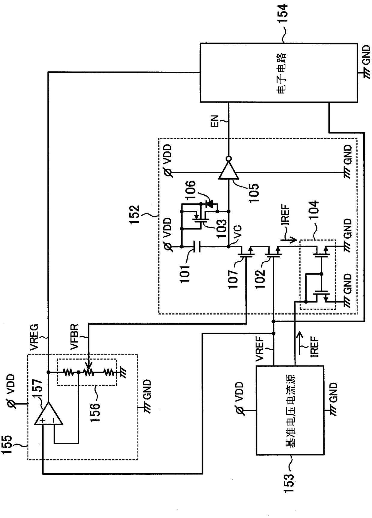
[0038] image 3 It is a circuit diagram including the voltage detection circuit according to the second embodiment of the present invention. This implementation is in figure 1 The voltage output circuit 155 and the second switching element 107 are added to the structure of.
[0039] The voltage output circuit 155 is a circuit that is connected to the power supply voltage VDD and the ground voltage GND and operates, generates a regulated voltage VREG based on the reference voltage VREF, and supplies the regulated voltage VREG as an internal power supply voltage to the electronic circuit 154, for example An amplifier (operational amplifier: operational amplifier) 157 and a resistance dividing circuit 156 are formed. For example, the power supply voltage VDD is 3.3V, and the regulation voltage VREG is 1.8V. The resistance division circuit 156 has a function of generating a feedback voltage to the OP amplifier 157 based on the adjustment voltage VREG, and adjusting the adjustment ...
no. 3 Embodiment approach 》
[0046] Figure 5 It is a circuit diagram including the voltage detection circuit according to the third embodiment of the present invention. This implementation is from image 3 In the structure of, the first switching element 102 is removed, and the second switching element 107 and the current mirror circuit 104 are directly connected.
[0047] According to the third embodiment, by detecting the adjustment feedback voltage VFBR and outputting the enable signal EN, it is possible to avoid a malfunction of the electronic circuit 154 that uses the adjustment voltage VREG as the internal power supply voltage.
[0048] The first to third embodiments have been described above, but the present invention can be modified in various ways. For example, in the case of detecting three or more voltages, a series circuit of three or more switching elements corresponding thereto may be inserted between the capacitive element 101 and the current mirror circuit 104.
[0049] In addition, when the a...
PUM
 Abstract
Description
Claims
Application Information