
Laser cutting head for strip steel

A technology of laser cutting head and cutting head, which is applied in the direction of laser welding equipment, welding equipment, metal processing equipment, etc., can solve the problems of reducing cutting speed and cutting quality, and small laser cutting kerf, so as to improve feasibility and processing accuracy , prolong life and ensure cleanliness

Active Publication Date: 2016-03-30
BAOSHAN IRON & STEEL CO LTD
View PDF8 Cites 1 Cited by
  • Summary
  • Abstract
  • Description
  • Claims
  • Application Information

AI Technical Summary

Problems solved by technology

4. The kerf of laser cutting is extremely small
The above nozzle designs for laser cutting all need to ensure that the center of the gas nozzle coincides strictly with the center of the laser, otherwise the cutting speed and cutting quality will be significantly reduced

Method used


Image

  • Laser cutting head for strip steel
  • Laser cutting head for strip steel
  • Laser cutting head for strip steel

Examples


Embodiment 1

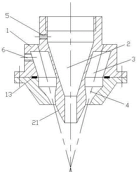
[0026] Such as figure 1 , 2 As shown, a laser cutting head for strip steel includes a cutting head body 1, the axis of the cutting head body 1 is provided with a laser passage 2, and a ring-shaped laser passage 2 is provided in the cutting head body 1. The air injection chamber 3, the purpose of the air injection chamber 3 is to assist the air flow to maintain a uniform pressure before entering the air injection structure 4, so in order to better achieve this purpose, the volume of the air injection chamber 3 is larger than the air injection structure 4 in the present invention The volume of the cutting head body 1 is provided with a pressure maintaining air inlet 5 and an injection air inlet 6, the pressure maintaining air inlet 5 communicates with the laser passage 2, and the injection air inlet 6 is connected with the air injection chamber 3 connected, the airflow entering the pressure-holding air inlet 5 provides a certain positive pressure for the laser passage 2, which ...

Embodiment 2

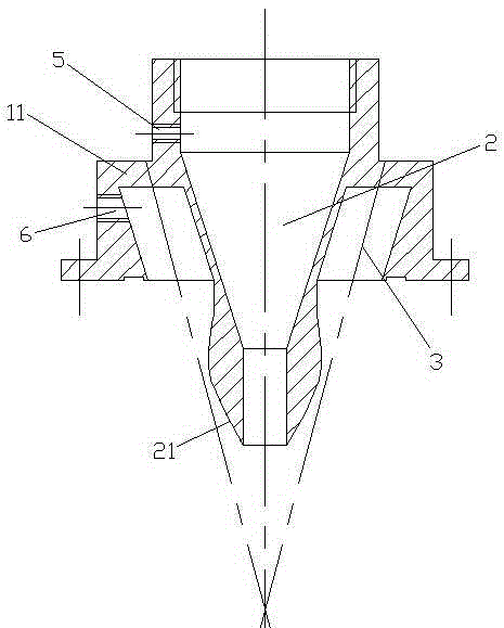
[0031] Such as Figure 5 , 6 , 7, and 8, a laser cutting head for strip steel, the difference between embodiment 2 and embodiment 1 is that the cutting head body 1 is composed of two parts, an upper structure 11 and a lower structure 12, and the The laser passage 2 and the upper structure 11 are integrated, the lower structure 12 is set outside the laser passage 2, the lower structure 12 is sealed and fixedly connected to the lower end surface of the upper structure 11, and a sealing seal is arranged between the upper structure 11 and the lower structure 12. circle 13, the air injection structure 4 is composed of a number of air injection holes provided on the lower structure 12, and the number of air injection holes is an annular array centered on the axis of the laser passage 2. In this embodiment, there are four air injection holes. indivual.


PUM


Abstract

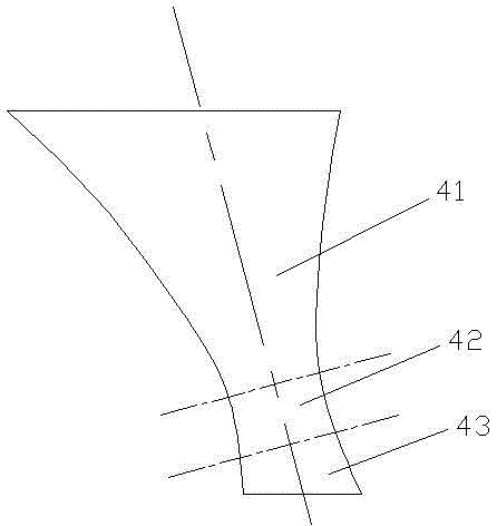
The invention relates to the field of laser cutting, particularly to a high-speed strip steel laser cutting head. The strip steel laser cutting head comprises a cutting head body, the axial center of the cutting head body is provided with a laser passage, and a ring-shaped air spray cavity is formed inside the cutting head body and around the laser passage; the side wall of the cutting head body is provided with a pressure maintaining air inlet hole and a jetting air inlet channel, wherein the pressure maintaining air inlet hole is communicated with the laser passage, and the jetting air inlet channel is communicated with the air spray cavity; the bottom of the cutting head body is provided with an air spray structure communicated with the air spray cavity, the air spray structure is centrally-symmetric around the axis of the laser passage, and the vertical cross section of the air spray structure is composed of a retracting cavity, a neck component and a diffusing cavity from the top to the bottom. According to the strip steel laser cutting head, an air spray purging and the laser passage are separated, and no cutting dust entering the laser passage is guaranteed through the wall attachment effect, so that the cleanliness of the laser passage can be ensured, and the beam quality can be improved, the service life of associated optical elements can be prolonged.

Description

technical field [0001] The invention relates to the field of laser cutting, in particular to a laser cutting head for high-speed laser cutting of strip steel. Background technique [0002] Since the 1970s, laser cutting has gradually been applied in enterprise production. The advantages of laser cutting are: 1. Laser cutting is a non-contact optical thermal processing, known as "a universal tool that never wears out". The workpiece can be nested or nested in any form to make full use of raw materials. Due to non-contact processing, there is no deformation of the processed parts. 2. High efficiency of laser cutting. The high efficiency makes the processing cost of a single piece reduce geometrically, even lower than the traditional processing method. 3. Laser cutting does not require tools and molds. Under the control of the computer, it can directly realize the flexible processing of plate and shell parts with arbitrary shapes in two-dimensional and three-dimensional, e...

Claims


Application Information

Patent Timeline
Patent Type & Authority Patents(China)
IPC IPC(8): B23K26/14B23K26/38
CPCB23K26/14B23K26/38
Inventor 王英杰赵春涛李山青王英睿
Owner BAOSHAN IRON & STEEL CO LTD
Learn More