
Primary mold

An integrated, cavity technology, used in glass blowing molds, glass production, etc., can solve the problems of low production efficiency, reduced glass bottle production efficiency, long time consumption, etc., to improve production efficiency and reduce the movement and reset of the funnel. , the effect of improving production quality

Inactive Publication Date: 2014-11-12
DEQING CAIFU GLASS
View PDF6 Cites 4 Cited by
  • Summary
  • Abstract
  • Description
  • Claims
  • Application Information

AI Technical Summary

Problems solved by technology

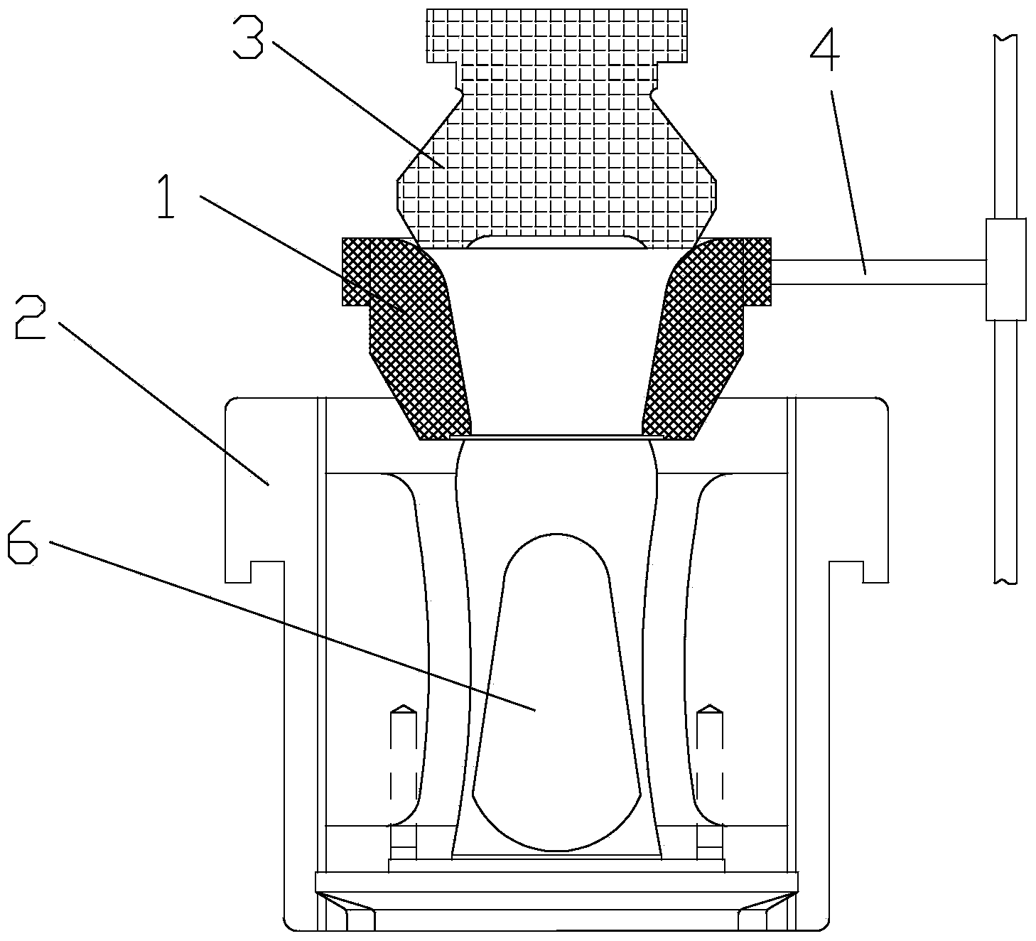
Specifically, as figure 1 As shown, open the distributing machine so that the melted glass frit 6 falls from the distributing machine. At this time, the funnel 1 is placed at the opening of the upper end of the primary mold 2, so that the glass frit enters the inner cavity of the primary mold 2 through the guidance of the funnel 1 , then place the bulkhead 3 on the funnel 1, and finally remove the bulkhead 3 and the funnel 1, and the preliminarily formed glass bottle waits for the next step of the process, the funnel 1 is arranged on the funnel arm 4, and the funnel arm 4 drives The funnel 1 moves to the upper opening of the primary mold 2, and then the funnel arm 4 drives the funnel 1 to move away from the top of the primary mold 2. At this time, the funnel 1 completes the guiding function of the glass frit once; however, the funnel arm is used to drive the funnel to move and reset in the market It takes about 1.5S, and it takes about 7.5S for each group of machines to produce a bottle, which accounts for 20% of the production time of the whole glass bottle. It can be seen that the setting of this funnel reduces the production efficiency of glass bottles
[0003] In order to solve the above-mentioned problems of long time consumption and low production efficiency caused by the funnel arm driving the funnel to introduce the glass frit into the initial mold and the funnel arm driving the funnel to reset, the present invention proposes a belt that can shorten the time consumption and improve the production efficiency of glass bottles. The initial mold of the funnel

Method used


Image

  • Primary mold
  • Primary mold
  • Primary mold

Examples


Embodiment

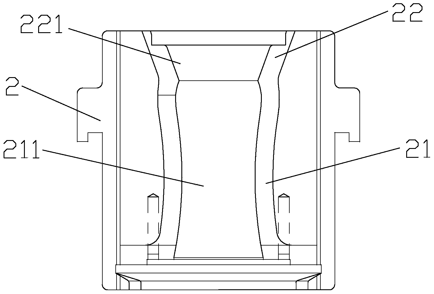
[0014] Embodiment: a kind of preliminary model, as figure 2 As shown, the primary mold 2 is provided with a cavity 211 , and a funnel-shaped feed cavity 221 is formed at the upper opening of the primary mold 2 , and the feed cavity 221 communicates with the cavity 211 .

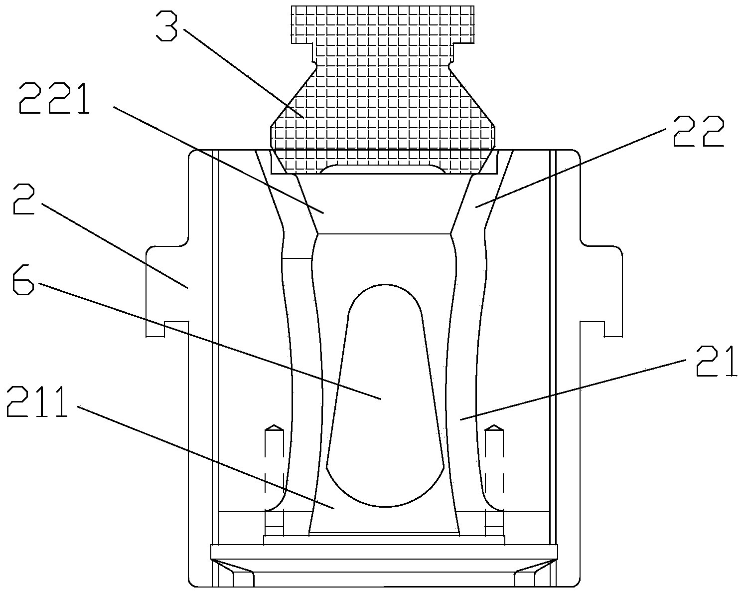
[0015] Specifically, the bottom of the blank mold 2 is a bottle forming part 21, the cavity 211 is arranged in the bottle forming section 21, the top of the blank mold 2 is a feeding part 22, and the feeding chamber 221 is arranged in the feeding part 22, The bottle forming part 21 and the feeding part 22 are integrally formed, and the bottom of the feeding cavity 221 communicates with the top of the cavity 211 .

[0016] The specific working process is as follows: image 3 As shown, the distributing machine is opened so that the melted glass frit 6 falls from the distributing machine, and the glass frit directly enters the cavity 211 through the guide of the feeding chamber 221, and then the bulkhead 3 is ...


PUM


Abstract

The invention relates to a primary mold. A cavity is formed in the primary mold. A hopper-shaped feeding cavity is formed in an opening in the upper end of the primary mold. The feeding cavity is communicated with the cavity. The lower portion of the primary mold is a bottle forming portion. The cavity is arranged in the bottle forming portion. The upper portion of the primary mold is a feeding portion. The feeding cavity is arranged in the feeding portion. The bottle forming portion and the feeding portion are integrally formed. The bottom of the feeding cavity is communicated with the top of the cavity. Compared with the prior art, the hopper-shaped feeding cavity is directly formed in the opening in the upper end of the primary mold, and the primary mold and the feeding cavity are integrally formed, so that time consumed when a hopper arm drives a hopper to reach the opening in the upper end of the primary mold and the hopper arm drives the hopper to be reset in the prior art is saved, hopper displacement and reset actions are reduced, and glass bottle production efficiency is improved on the same condition.

Description

technical field [0001] The invention relates to glass bottle blank processing accessories, in particular to a primary mold with a funnel. Background technique [0002] At present, in the production and manufacturing process of glass bottles, it is necessary to make the molten glass go through the cooperation of the initial mold, the die and the bulkhead to make the glass bottle take shape. Specifically, as figure 1 As shown, open the distributing machine so that the melted glass frit 6 falls from the distributing machine. At this time, the funnel 1 is placed at the opening of the upper end of the primary mold 2, so that the glass frit enters the inner cavity of the primary mold 2 through the guidance of the funnel 1 , then place the bulkhead 3 on the funnel 1, and finally remove the bulkhead 3 and the funnel 1, and the preliminarily formed glass bottle waits for the next step of the process, the funnel 1 is arranged on the funnel arm 4, and the funnel arm 4 drives The funn...

Claims


Application Information

Patent Timeline
IPC IPC(8): C03B9/347
CPCY02P40/57
Inventor 陈向明
Owner DEQING CAIFU GLASS
Learn More