Check patentability & draft patents in minutes with Patsnap Eureka AI!

Fan speed control system

A technology for controlling system and fan speed, which is applied in pump control, cooling/ventilation/heating transformation, modification with gaseous coolant, etc. It can solve problems such as the inability to guarantee the system ambient temperature, the inability to adjust the fan speed, and the side effects of system stability.

Inactive Publication Date: 2014-11-12
HONG FU JIN PRECISION IND (SHENZHEN) CO LTD +1
View PDF0 Cites 12 Cited by
  • Summary
  • Abstract
  • Description
  • Claims
  • Application Information

AI Technical Summary

Problems solved by technology

[0003] However, in the above control scheme, if there is a problem with the platform management chip, it will cause the fan speed to be unable to be adjusted. Not only cannot the ambient temperature of the system be kept at a normal value, but the noise and vibration caused by the fan may also exceed the designer’s Expected, have a great side effect on the stability of the system

Method used


Image

  • Fan speed control system

Examples


Embodiment Construction

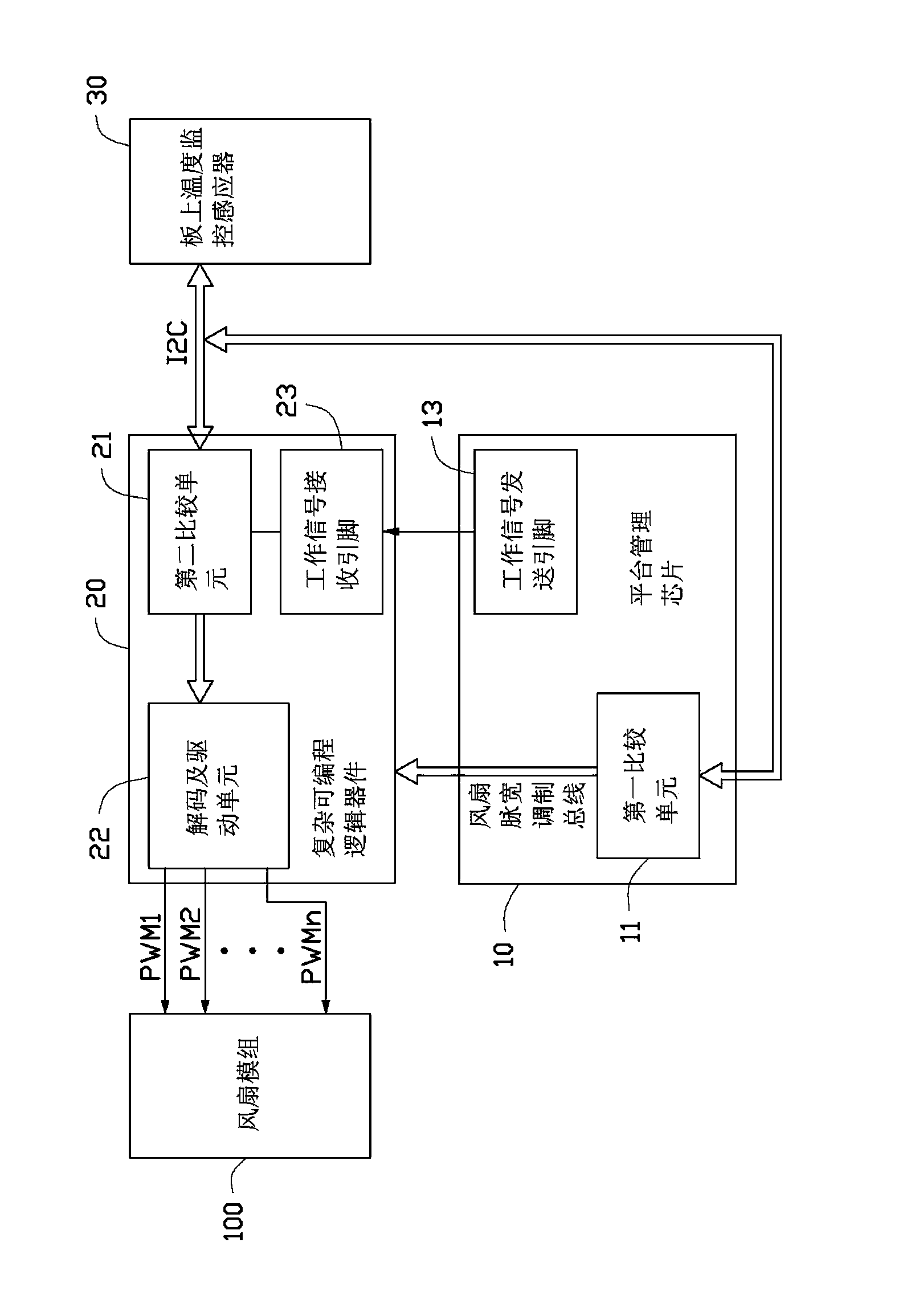
[0017] Please refer to figure 1 , in a preferred embodiment of the present invention, a fan speed control system is used to control the speed of a fan module 100 . The fan speed control system includes a BMC 10 , a CPLD (Complex Programmable Logic Device, Complex Programmable Logic Device) 20 and an on-board temperature monitoring sensor 30 .

[0018] The on-board temperature monitoring sensor 30 is used to monitor the temperature of each electronic component in an electronic device, and transmit the monitored temperature signal to the BMC 10 or the CPLD 20 .

[0019] The BMC 10 includes a first comparing unit 11 and a working signal sending pin 13 . The input terminal of the first comparison unit 11 is passed through an I 2 The C bus is connected to the temperature monitoring sensor 30 on the board, and the output terminal of the first comparison unit 11 is connected to the CPLD 20 through a fan PWM bus. The first comparison unit 11 is preset with the reference temperature...


PUM


Abstract

A fan speed control system includes a BMC, a CPLD, and a temperature sensor. The BMC includes an operation signal sending pin. The CPLD includes an operation signal receiving pin connected to the operation signal sending pin. The temperature sensor is configured for detecting temperatures of electronic components. When the BMC fails to operate normally, the operation signal sending pin sends a BMC_fail signal to the operation signal receiving pin, the temperature sensor sends the detected temperatures to the CPLD. The CPLD compares the detected temperatures with the corresponding preset standard temperatures and adjusts the speed of the fan module according to a comparing result.

Description

technical field [0001] The invention relates to a fan control system, in particular to a fan speed control system. Background technique [0002] At present, the heat dissipation system of the server is inseparable from the fan, so the control of the fan speed has become a common topic for designers. In the current mainstream design, BMC (Board Management Chip, platform management chip) is generally used as the speed control of the fan. By knowing the temperature of each position or device on the current motherboard, the BMC sends the most suitable fan speed PWM signal to the fan according to the preset temperature and fan speed comparison table, so that the current fan speed can be reduced or maintained. The temperature can also ensure that the noise and vibration of the fan have the least impact on the system. [0003] However, in the above control scheme, if there is a problem with the platform management chip, it will cause the fan speed to be unable to be adjusted. Not...

Claims


Application Information

Patent Timeline
Patent Type & Authority Applications(China)
IPC IPC(8): F04D27/00
CPCH05K7/20209H05K7/20136
Inventor 喻明
Owner HONG FU JIN PRECISION IND (SHENZHEN) CO LTD
Features
  • R&D
  • Intellectual Property
  • Life Sciences
  • Materials
  • Tech Scout
  • Unparalleled Data Quality
  • Higher Quality Content
  • 60% Fewer Hallucinations
Learn More