Method and apparatus for braking and stopping vehicles having an electric drive

a technology of electric drive and braking system, which is applied in the direction of braking system, instruments, analogue processes for specific applications, etc., can solve the problems of inadequacies, inability to adapt to electric drive configurations, and inability to optimize the dual braking strategy described above, so as to reduce the need for conventional friction brakes and avoid conventional friction brakes.

Inactive Publication Date: 2006-03-02
FORD MOTOR CO
View PDF26 Cites 42 Cited by
  • Summary
  • Abstract
  • Description
  • Claims
  • Application Information

AI Technical Summary

Benefits of technology

[0007] One advantage of the invention is that the braking system can be used with reduced need for conventional friction brakes. Another advantage lies in the ability of the present braking system to decelerate the vehicle down to and including zero speed, and maintain the vehicle at a complete stop under various driving conditions, such as on a grade, using the speed control loop of the electric drive. A still further advantage of the invention is that the need for conventional friction brakes may be completely avoided.
[0008] In accordance with a first embodiment of the invention, a method is provided for braking and stopping a vehicle having at least one traction wheel driven by an electric motor. Braking and stopping is achieved by sensing a speed parameter related to the speed of the vehicle, sensing a commanded braking rate, generating a motor control signal using the sensed speed parameter and commanded braking rate, producing a negative torque using the electrical drive motor, applying braking forces to the traction wheels using the negative torque, and controlling the amount of negative torque produced by the electric drive motor using the motor control signal to achieve the commanded braking rate. The motor control signal may include a torque command signal, a speed command signal or a combination of these two signals. The torque command signal can be used to control the motor until the vehicle decelerates to a pre-selected speed, following which a speed control signal is used for motor control. The motor control signal is based on torque commands determined by the position of the vehicle's brake and accelerator pedals. The sensed speed parameter may include either the speed of the drive motor, the speed of at least one wheel of the vehicle, or a combination of these sensed speeds.
[0009] In accordance with a second embodiment of the invention, a system is provided for braking and stopping a vehicle powered by an electric motor driving at least one traction wheel. The system includes a closed loop speed control loop whose speed command is a zero speed signal. This closed loop system features modification of its control signal (torque command signal for the electric drive) by a bipolar torque limit signal-pair. The limit signal-pair is directly derived from a torque command that is obtained by the vehicle system controller, with the accelerator and brake pedals as inputs. The torque command of the vehicle system controller may be used for driving and deceleration at higher speeds, but the torque-limited speed control loop is used for bringing the vehicle to a stop.
[0010] These non-limiting features, as well as other advantages of the present invention may be better understood by considering the following details of a description of a preferred embodiment of the present invention. In the course of this description, reference will frequently be made to the attached drawings.

Problems solved by technology

The dual braking strategy described above may not be optimum for certain types of electric drive configurations, and may not be appropriate for configurations where it is desirable to completely avoid friction braking components.

Method used


Image

  • Method and apparatus for braking and stopping vehicles having an electric drive
  • Method and apparatus for braking and stopping vehicles having an electric drive
  • Method and apparatus for braking and stopping vehicles having an electric drive

Examples


Embodiment Construction

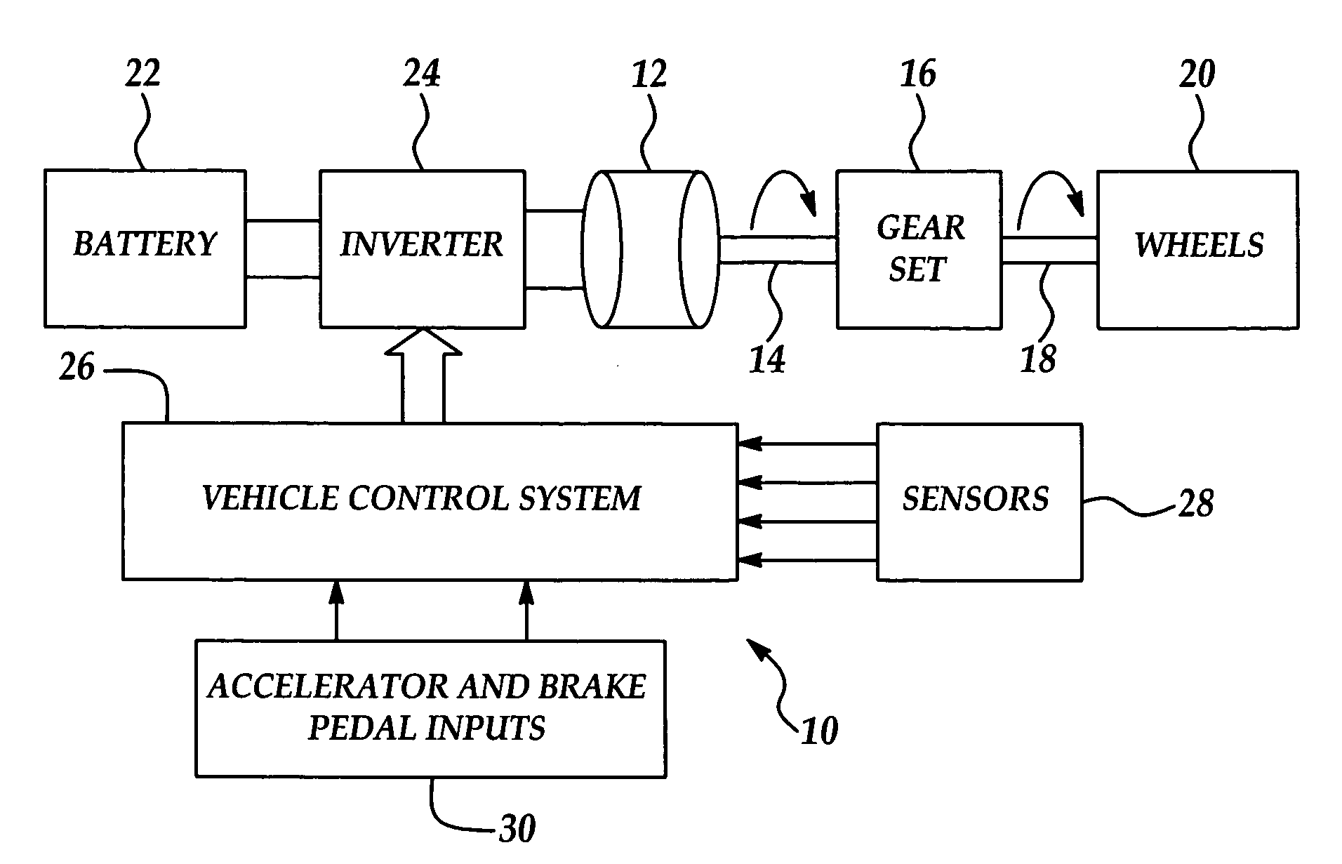
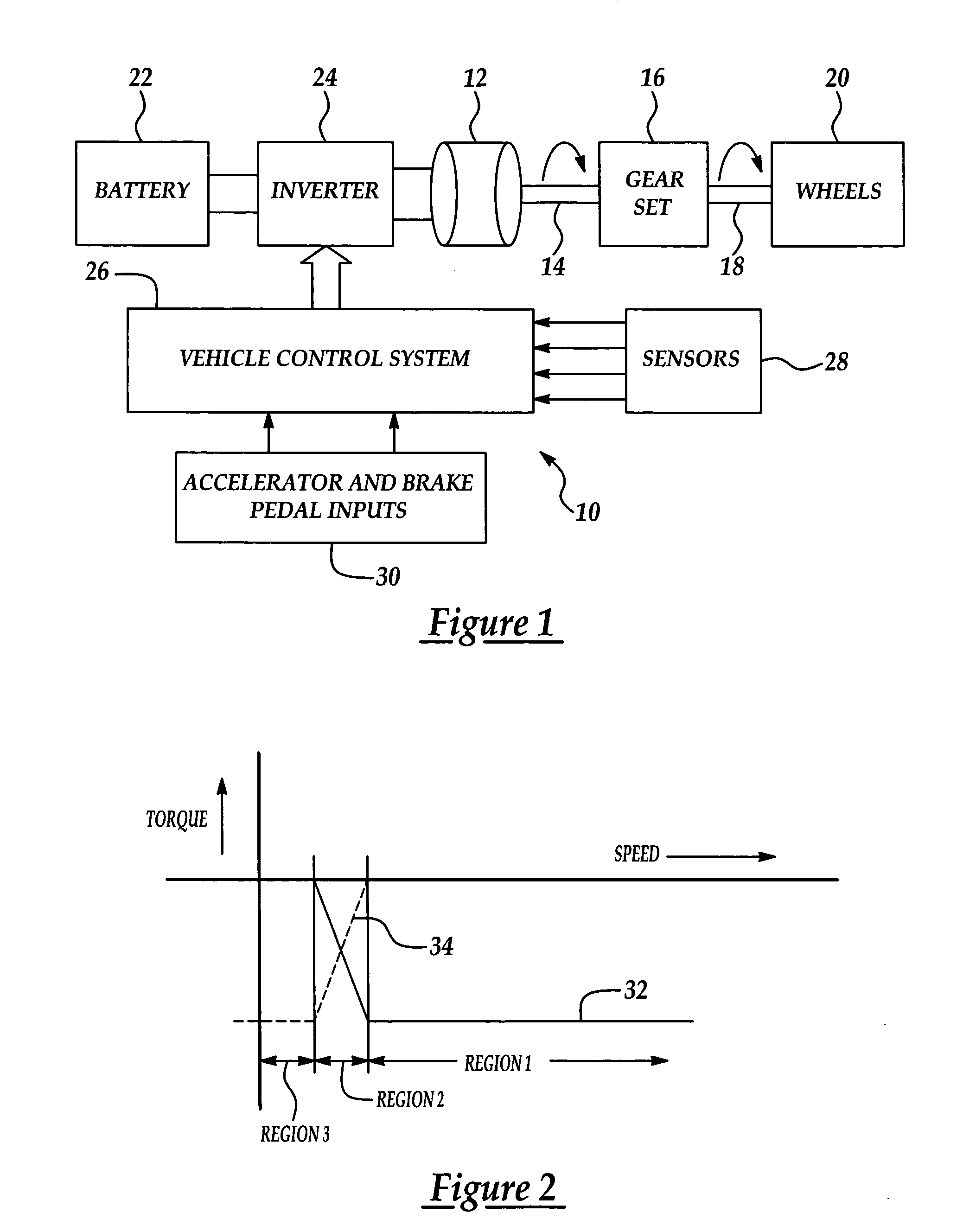
[0019] The invention relates to a method and apparatus for decelerating, braking and stopping a vehicle equipped with an electric drive system which includes an electric motor. A typical electric drive system 10 is shown in FIG. 1. An electric motor 12 mounted on the vehicle's chassis has an output drive shaft 14 which is connected through a differential gear-set 16 to a drive axle 18 carrying one or more traction wheels 20. Energy for powering the motor 12 is derived from an on-board storage battery 22 which provides DC power that is converted by an inverter 24 into AC power used to drive the motor 12. Although an AC motor 12 has been disclosed here, it should be noted that the present invention is suitable for use with a variety of DC and poly-phased AC motors. A vehicle control system 26 coordinates and controls the operation of the energy storage and drive components, and manages system functions such as charging, engine starting and stopping and regenerative braking. The vehicl...


PUM


Abstract

A method and apparatus are provided for braking and stopping a vehicle whose powertrain includes an electric drive. The electric drive is used to generate braking torque which is used to decelerate the vehicle down to a full stop. The braking torque is achieved using any of several closed loop speed control systems. The system can be used as a substitute for or as a supplement to conventional friction bakes.

Description

FIELD OF THE INVENTION [0001] This invention generally relates to vehicles with electric drive systems, and deals more particularly with a method and apparatus for braking and stopping the vehicle using the electric drive. BACKGROUND OF THE INVENTION [0002] Many recent designs of electric powered and hybrid electric powered vehicles employ a regenerative braking system in order to increase operating efficiency. During a braking event, the electric motor which normally drives one or more traction wheels is switched to operate as an electrical generator. Using the momentum and kinetic energy of the vehicle, the electric drive motor generates electricity that may be used to recharge on-board energy storage systems, such as batteries and ultra capacitors, power accessories, or power auxiliary on-board systems. [0003] Regenerative braking systems are particularly effective in recovering energy during city driving, where driving patterns of repeated acceleration and decelerations are comm...

Claims


Application Information

Patent Timeline
Patent Type & Authority Applications(United States)
IPC IPC(8): G06G7/76B60K6/20B60L7/18B60T13/58B60W10/08B60W30/18
CPCB60L7/18B60T13/586B60W10/08Y10S903/947B60W2540/10B60W2540/12B60W30/18127B60L7/14B60L15/2009Y02T10/64Y02T10/72
Inventor PRAKASH, RAJCROMBEZ, DALEWORREL, PETERGARG, VIJAY
Owner FORD MOTOR CO
Why Eureka
Try Eureka