
Improved structure of locking mechanism between vertical tube and adjusting tube for fitness equipment

A technology of locking mechanism and fitness equipment, applied in the connection of rods, connecting components, gymnastics equipment, etc., can solve the problems of loose riser, thread wear of bolts, safety accidents, etc., and achieve the effect of convenient operation

Inactive Publication Date: 2014-11-12
KUSN LIYAN METAL PRODS
View PDF7 Cites 0 Cited by
  • Summary
  • Abstract
  • Description
  • Claims
  • Application Information

AI Technical Summary

Problems solved by technology

[0002] At present, the standpipe and adjustment tube used in fitness equipment are mainly used for height adjustment at the handlebars and seat cushions. The common fixed locking mechanism between the standpipe and the adjustment tube is a bolt with an operating handle. Tighten the standpipe to achieve a fixed position with the adjustment pipe. However, after long-term use of this locking method, the thread of the bolt is prone to wear and tear, which will cause the standpipe to loosen and cause a safety accident.
In response to the above defects, a method has been developed that uses the end face of the locking block to tighten the standpipe so as to secure the standpipe firmly. However, after long-term use of this structure, the end face of the locking block is easy to wear, resulting in a mismatch between the locking block and the standpipe. , making it impossible to lock the riser

Method used


Image

  • Improved structure of locking mechanism between vertical tube and adjusting tube for fitness equipment
  • Improved structure of locking mechanism between vertical tube and adjusting tube for fitness equipment
  • Improved structure of locking mechanism between vertical tube and adjusting tube for fitness equipment

Examples


Embodiment Construction

[0028] Embodiments of the present invention will be described in detail below in conjunction with the accompanying drawings.

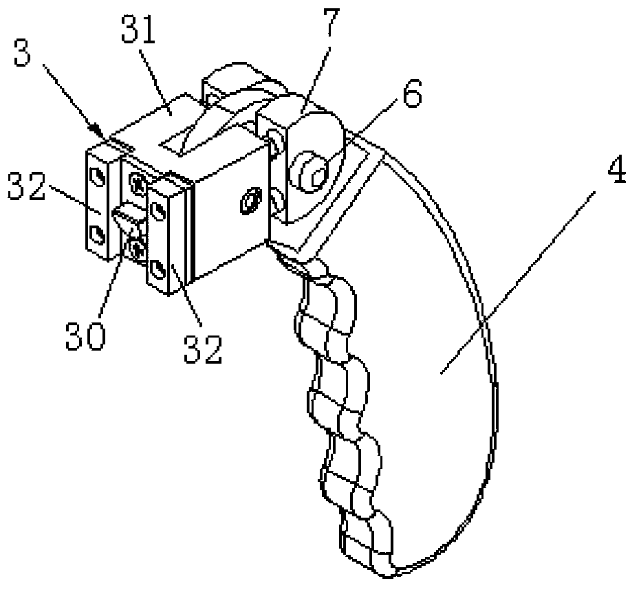
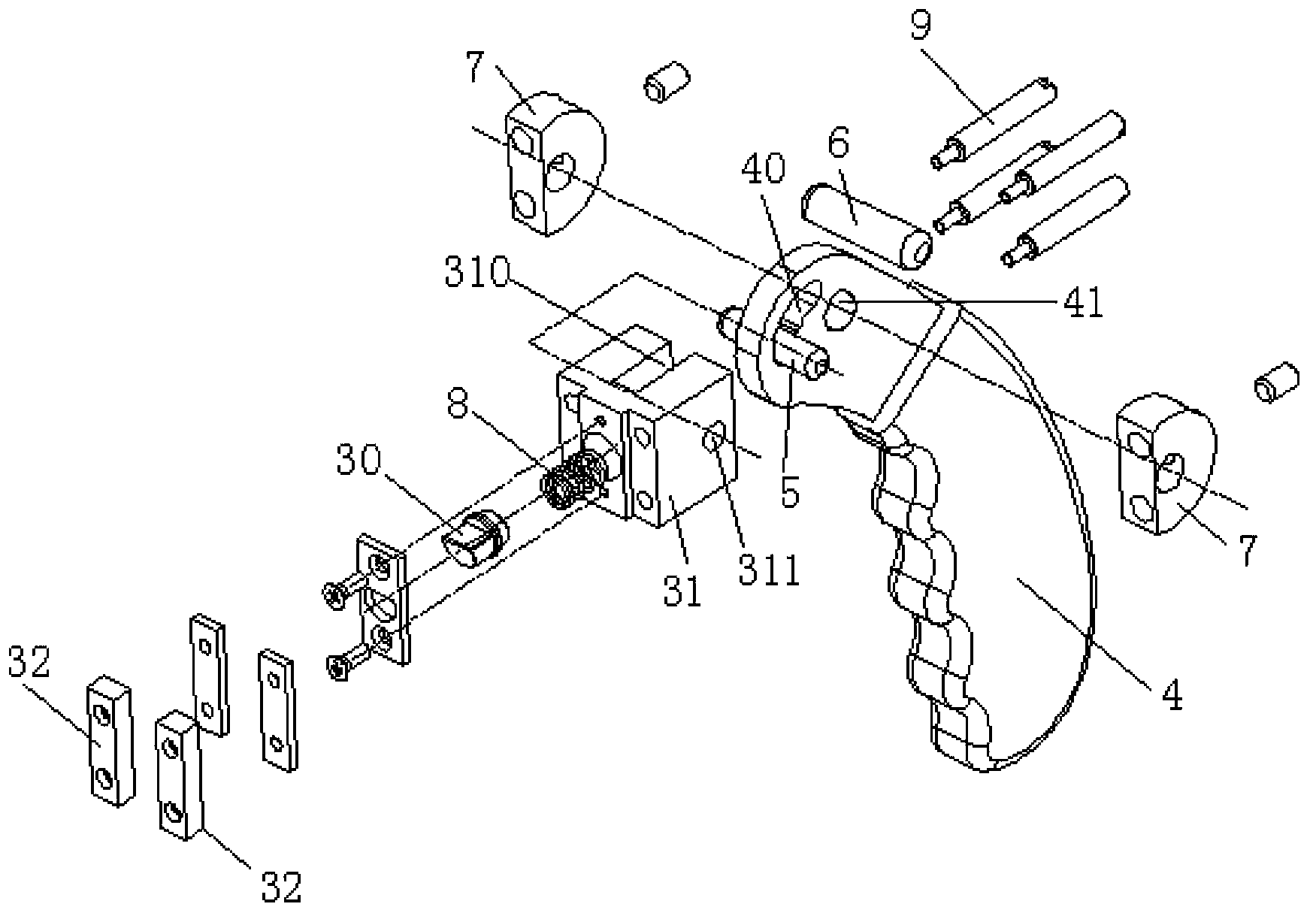
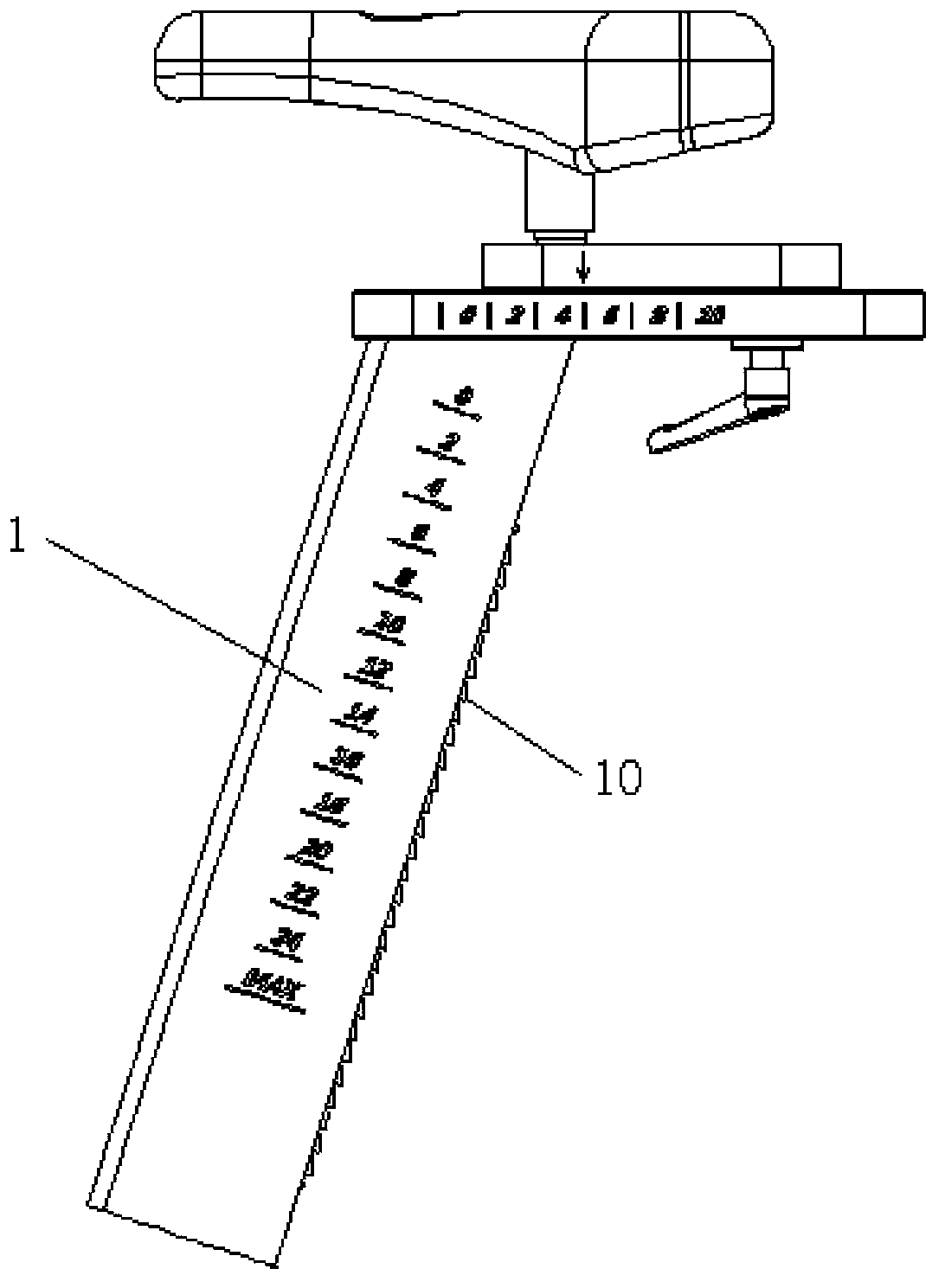
[0029] The improved structure of the locking mechanism between the standpipe and the adjustment pipe for fitness equipment provided by the present invention, the standpipe 1 is freely inserted in the adjustment pipe 2, and the position of the standpipe 1 relative to the adjustment pipe 2 is fixed by the locking mechanism , the locking mechanism includes a sliding block 3, the adjustment tube is provided with a sliding tube for the sliding block 3 to move freely, and the sliding block 3 can move freely in the sliding tube along the axial direction of the sliding tube In addition, the sliding pipe opens to the standpipe 1, and the sliding block 3 can just break away from and press against the standpipe 1; the sliding block 3 includes a lock tongue 30 and a pressing block 31, and the lock tongue 30 is elastically stretchable and positioned On the side of ...


PUM


Abstract

The invention discloses an improved structure of a locking mechanism between a vertical tube and an adjusting tube for fitness equipment. The vertical tube is freely inserted in the adjusting tube, the vertical tube is fixed relative to the position of the adjusting tube through the locking mechanism, and the locking mechanism comprises a spring bolt and a pressing block. The spring bolt elastically stretches out and draws back and is positioned at the side, facing the vertical tube, of the pressing block, a ratchet face is formed on the outer side wall, facing the spring bolt, of the vertical tube in the axial direction of the vertical tube, and the ratchet face is provided with a plurality of tooth notches in the same inclined direction. The end, facing the vertical tube, of the spring bolt can be just separated from and blocked in any tooth notch of the ratchet face. In addition, a pair of long-strip-shaped limiting blocks is detachably and fixedly arranged on the side, facing the vertical tube, of the pressing block, the spring bolt is movably placed between the long-strip-shaped limiting blocks, and the long-strip-shaped limiting blocks can be separated from and pressed on the vertical tube under the effect of the pressing block. Adjustment and positioning of the position between the vertical tube and the adjusting tube can be effectively achieved through matching of the spring bolt and the long-strip-shaped limiting blocks, and the locking mechanism has multiple working gears, and is convenient to operate and diversified.

Description

technical field [0001] The invention relates to the technical field of locking mechanisms, and specifically provides an improved structure of a locking mechanism between a riser for fitness equipment and an adjustment tube. Background technique [0002] At present, the standpipe and adjustment tube used in fitness equipment are mainly used for height adjustment at the handlebars and seat cushions. The common fixed locking mechanism between the standpipe and the adjustment tube is a bolt with an operating handle. Tighten the standpipe to achieve a fixed position with the adjustment pipe. However, after long-term use of this locking method, the thread of the bolt is prone to wear and tear, which will cause the standpipe to loosen and cause a safety accident. In response to the above defects, a method has been developed that uses the end face of the locking block to tighten the standpipe so as to secure the standpipe firmly. However, after long-term use of this structure, the e...

Claims


Application Information

Patent Timeline
Patent Type & Authority Applications(China)
IPC IPC(8): F16B7/14A63B22/08
Inventor 黄钦霖
Owner KUSN LIYAN METAL PRODS
Learn More