
Deformation correcting device for welded tubes

A welded pipe and orthopedic technology, applied in the field of welded pipe orthopedic devices, can solve the problems of affecting the orthopedic effect, shortening the life of the orthopedic roller, large flexural stress, etc., and achieve the effect of good orthopedic effect.

Inactive Publication Date: 2014-11-19
JIANGSU LONGYUAN METAL TECH
View PDF6 Cites 6 Cited by
  • Summary
  • Abstract
  • Description
  • Claims
  • Application Information

AI Technical Summary

Problems solved by technology

The positions where the welded pipes are severely deformed during welding may be different on different production lines, but the shaping rollers of the existing orthopedic devices are not adjustable relative to the circumferential position of the pipe, which makes the bending stress of the roller shaft of the orthopedic rollers larger. Large, affecting the shaping effect and shortening the life of the shaping roller

Method used


Image

  • Deformation correcting device for welded tubes
  • Deformation correcting device for welded tubes
  • Deformation correcting device for welded tubes

Examples


Embodiment Construction

[0019] Specific embodiments of the present invention will be described in detail below with reference to the accompanying drawings.

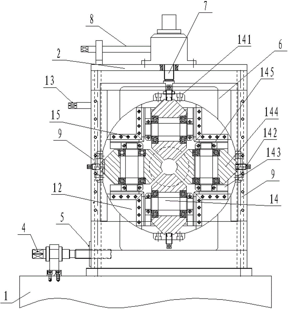
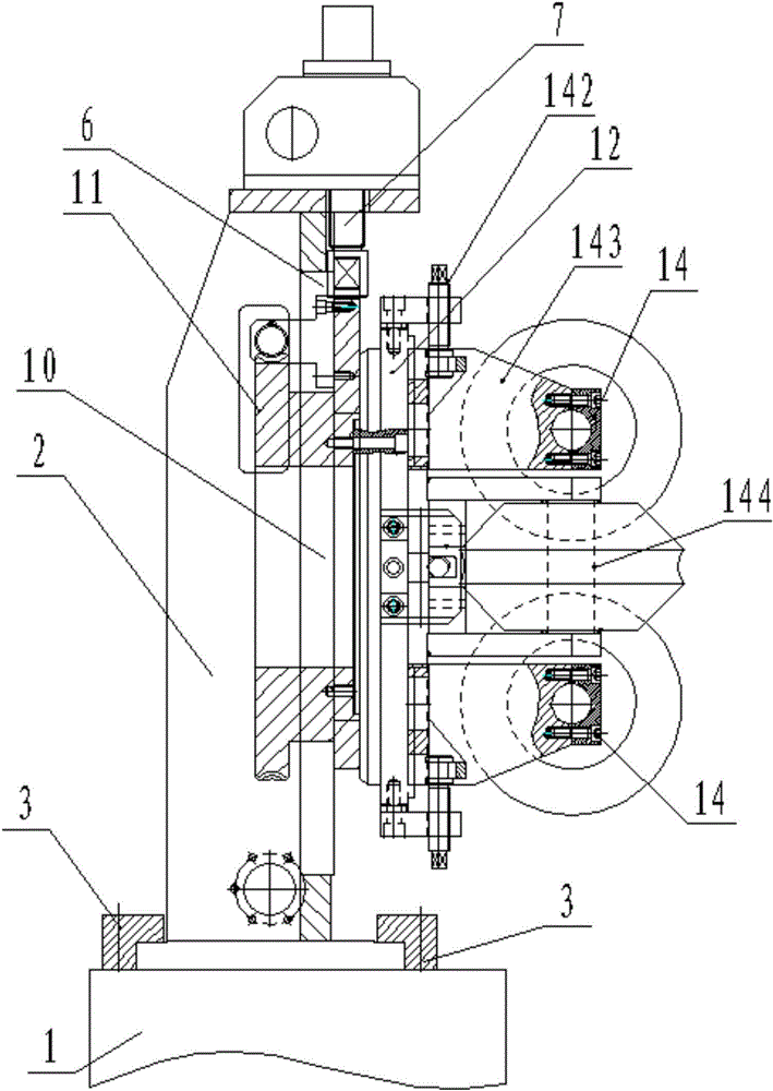
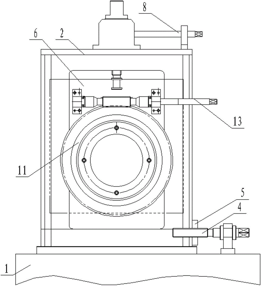
[0020] like Figure 1-3 As shown, a welded pipe orthopedic device includes a gantry 2 movably arranged on an installation base 1, the installation base 1 is provided with pressure plates 3 covering both sides of the bottom plate of the gantry 2, and the installation base 1 is on the gantry frame. 2 is provided with a lead screw 4, the lead screw 4 is connected with the gantry frame 2 through threads, and an adjusting nut 5 is provided on the lead screw 4 on the outer casing of the gantry frame 2.

[0021] The gantry frame 2 is movably provided with a movable seat 6 that can move up and down, the upper part of the movable seat 6 is provided with a screw 7, and the part of the upper part of the screw 7 that passes through the top plate of the gantry frame 2 is sleeved with a worm gear (not shown in the figure), and the gantry The top plate of the...


PUM


Abstract

The invention discloses a deformation correcting device for welded tubes. The deformation correcting device is convenient to use and good in deformation correcting effect. The device comprises a portal frame arranged on an installing base, a movable base which can move in the vertical direction is movably arranged in the portal frame, and a rotating shaft is arranged on the movable base. The rotating shaft is sleeved with a main worm gear and a rotating base, the movable base is provided with a main worm driving the main worm gear, and a through hole is formed in the center of the rotating base and used for allowing the welded tube to penetrate. Three or more shaping assemblies are evenly distributed in the circumferential direction of the through hole in the rotating base. Each shaping assembly comprises a fixing plate arranged on the rotating base, the fixing plates are connected with sliding bases through bolts, wherein the sliding bases move in the radial direction of the through hole, and shaping rollers are arranged on the sliding bases and are perpendicular to the moving direction of the sliding bases and rotate freely. Limiting pressing strips are arranged on the parts, on the two sides of each sliding base, of the rotating base. The shaping faces of the shaping rollers are circular arc surfaces of which the diameter is the same as the diameter of the peripheries of the welded tubes, and the total circular arc length of all the shaping faces accounts for over 80% of the length of the peripheries of the welded tubes.

Description

technical field [0001] The invention relates to an orthopedic device for a welded pipe. Background technique [0002] After the welded pipe is welded, due to the effect of welding thermal stress, the pipe will be deformed to a certain extent, and this deformation will directly affect the quality of the pipe. Therefore, the welded pipe needs to be corrected by a series of orthopedic devices to correct this deformation. The position where the welded pipe is seriously deformed during welding may be different on different production lines, but the shaping roller of the existing orthopedic device cannot be adjusted relative to the circumferential position of the pipe, which makes the roller shaft of the orthopedic roller more susceptible to flexural stress. large, affecting the shaping effect and shortening the life of the orthopedic roller. SUMMARY OF THE INVENTION [0003] The technical problem to be solved by the present invention is to provide an orthopedic device for a we...

Claims


Application Information

Patent Timeline
IPC IPC(8): B21D3/02
Inventor 郁仁兴刘咏孙惠忠
Owner JIANGSU LONGYUAN METAL TECH
Learn More