Multi-head punching device

A punching head and punching technology, applied in the field of sheet metal processing, can solve the problems of cumbersome adjustment of punching head position and slow processing speed, and achieve the effects of good adaptability, easy operation and improved work efficiency.

Inactive Publication Date: 2014-11-19
SUZHOU TIANYE MECHANICAL IND
View PDF7 Cites 12 Cited by
  • Summary
  • Abstract
  • Description
  • Claims
  • Application Information

AI Technical Summary

Problems solved by technology

The above-mentioned punching device or punching machine uses a single punch for punching, and its processing speed is relatively slow, and it is cumbersome to adjust the position of the punching head when changing the workpiece

Method used


Image

  • Multi-head punching device
  • Multi-head punching device

Examples


Embodiment Construction

[0013] The specific implementation manner of the present invention will be described below in conjunction with the accompanying drawings.

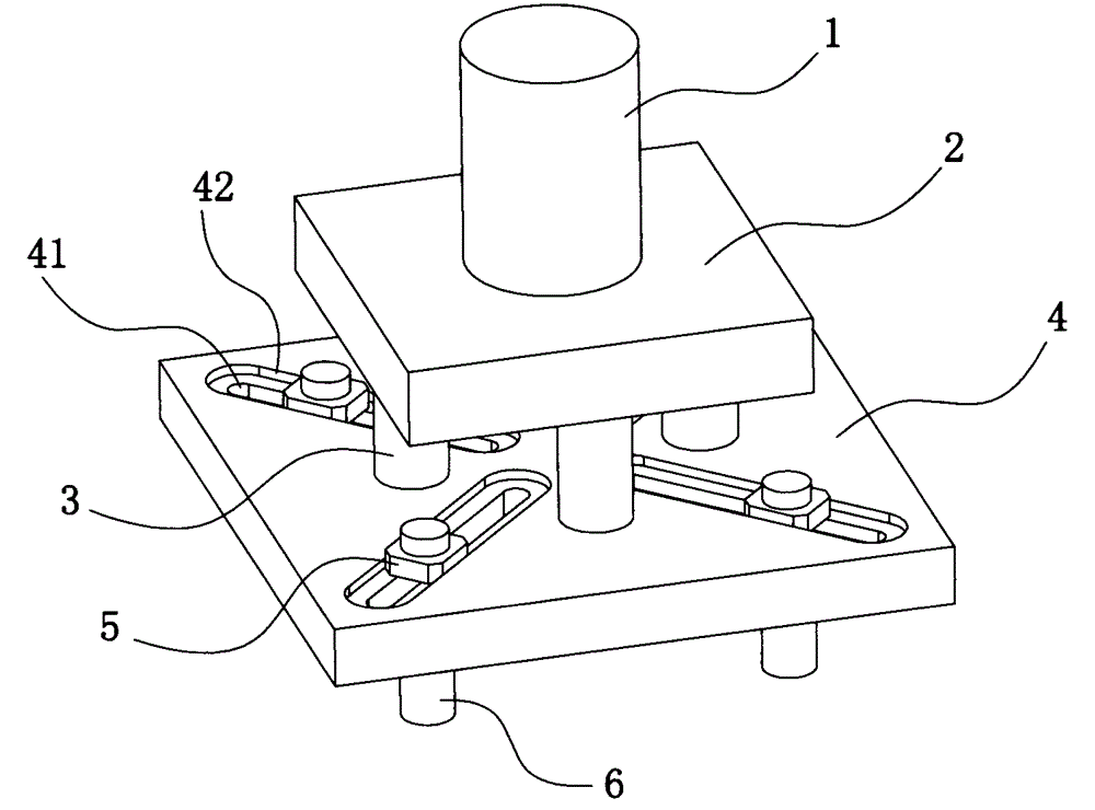
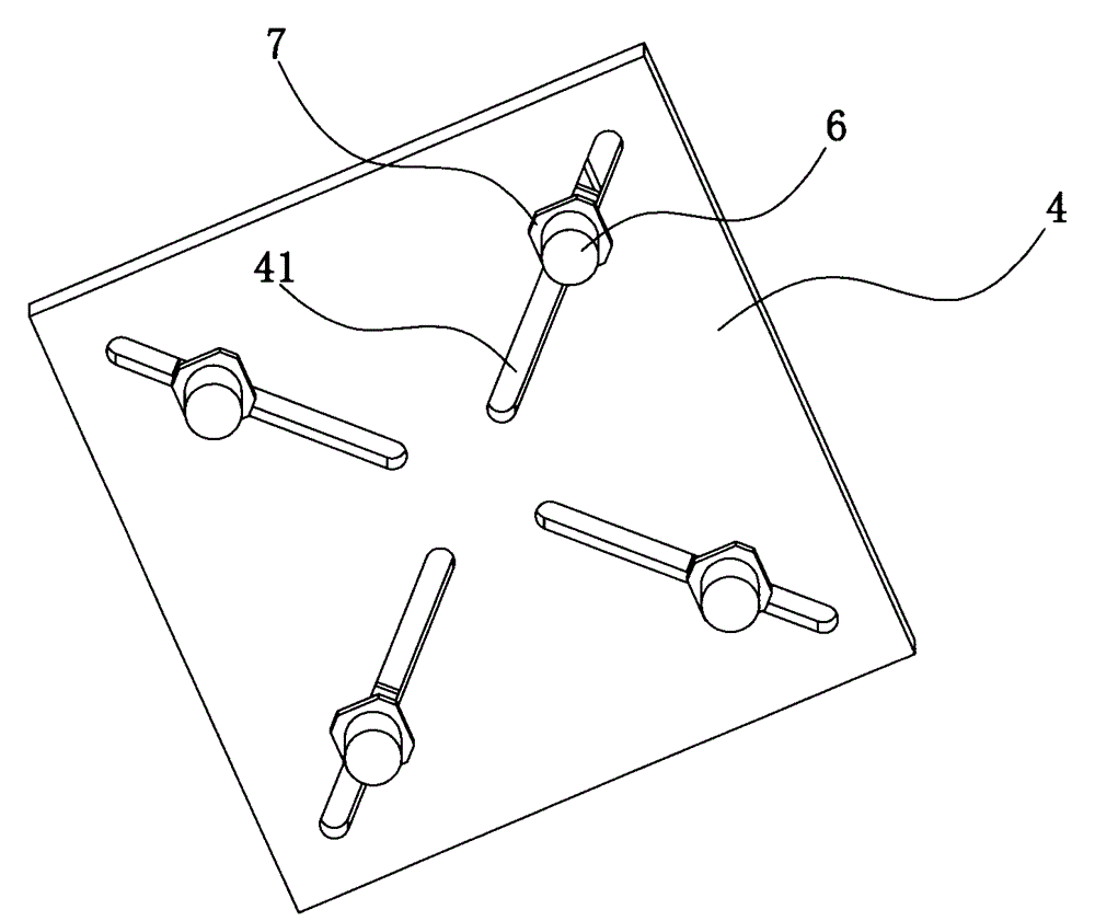
[0014] See figure 1 machine figure 2 , the present invention includes a punching drive device 1, an upper template 4 and a punching head 6 installed on a frame (not shown), the punching driving device 1 drives the upper template 4, and the lower surface of the upper template 4 is connected to the punching head 6. The punching driving device 1 drives the upper template 4 to drive the punching head 6 to reciprocate up and down. A fixed column 3 makes an operating space between the mounting plate 2 and the upper formwork 4, in order to improve the connection stability between the upper formwork 4 and the mounting plate 2, the fixed column 3 is arranged symmetrically with respect to the center of the upper formwork 4; A plurality of mounting grooves 41 are symmetrically arranged, and the mounting grooves 41 are arranged radially relative to...


PUM


Abstract

The invention relates to a multi-head punching device comprising a punching drive device disposed on a frame, an upper die plate and punching heads. The punching drive device drives the upper die plate. The punching heads are connected to the lower surface of the upper die plate. A mounting plate is connected between the punching drive device and the upper die plate. A plurality of fixing posts are fixedly connected between the mounting plate and the upper die plate. The upper die plate is provided with a plurality of mounting slots in a symmetrical manner. The mounting slots are arranged radially relative to the center of the upper die plate. Each punching head is fixedly connected in each mounting slot through an upper locking head and a lower locking head. The upper surface of each mounting slot is provided with a countersink is used for mounting the corresponding upper locking head. The multi-head punching device allows multiple holes to be punched once with the multiple punching heads, and operating efficiency is greatly improved; the upper die plate is radially provided with the mounting slots, the positions of the punching heads can be adjusted, operations are simple, one-time punching of variable position holes in different metal sheets is available, and adaptability is good; the upper die plate need not be replaced, and cost is lowered.

Description

technical field [0001] The invention relates to the technical field of sheet metal processing, in particular to a sheet metal punching machine. Background technique [0002] Existing punching devices or punching machines all include a frame, a bottom mold fixed on the frame, an upper template that moves up and down relative to the frame, and a punch corresponding to the bottom mold is fixed on the upper template. , the upper template is connected with the oil cylinder or cylinder that drives it to move up and down. Driven by the oil cylinder or air cylinder, the upper template drives the punch to move up and down relative to the bottom die, so as to punch out the required holes on the workpiece between the punch and the bottom die. The above-mentioned punching device or punching machine uses a single punch for punching, and its processing speed is relatively slow, and the position adjustment of the punching head is cumbersome when changing the workpiece to be processed. C...

Claims


Application Information

Patent Timeline
Patent Type & Authority Applications(China)
IPC IPC(8): B21D28/26B21D28/34
Inventor 蒋云泉
Owner SUZHOU TIANYE MECHANICAL IND
Why Eureka
Try Eureka