

Printing transmission roll
A technology of drive roller and elastic layer, which is applied in the direction of winding strips, layered products, thin material processing, etc., can solve the problems of poor wear resistance and short service life of drive rollers, prevent damage and improve use. Longevity and the effect of increasing wear resistance
- Summary
- Abstract
- Description
- Claims
- Application Information
AI Technical Summary
Problems solved by technology
Method used
Image

Examples
Embodiment Construction
[0012] In order to make the technical means, creative features, goals and effects achieved by the present invention easy to understand, the present invention will be further described below in conjunction with specific embodiments.
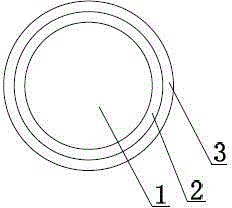
[0013] like figure 1 As shown, a printing drive roller includes a drive roller body 1 made of stainless steel, an elastic layer 2 made of rubber material is provided on the outer surface of the drive roller body 1, and the thickness of the elastic layer 2 is 2cm~4cm , the outer surface of the elastic layer 2 is provided with a wear-resistant layer 3 made of polytetrafluoroethylene material, the thickness of the wear-resistant layer 3 is 0.6mm~0.8mm, the cross-section of the driving roller body 1 is circular, and the elastic Layer 2 is compounded on the outer surface of the drive roller body 1 through an adhesive layer, and the wear-resistant layer 3 is compounded on the outer surface of the elastic layer 2 through an adhesive layer. The elastic la...
PUM
| Property | Measurement | Unit |
|---|---|---|
| thickness | aaaaa | aaaaa |
| thickness | aaaaa | aaaaa |
Abstract
Description
Claims
Application Information