Electromagnetic gas valve

A solenoid valve, valve body technology, applied in valve details, valve device, valve shell structure, etc., can solve problems such as poor sealing effect, small air output, and slow response of pneumatic components

Active Publication Date: 2014-11-19
瑞安市洛伊德机车部件有限公司
View PDF6 Cites 0 Cited by
  • Summary
  • Abstract
  • Description
  • Claims
  • Application Information

AI Technical Summary

Problems solved by technology

However, after this setting, due to the small air pipe, the gas can only produce a small air output when flowing through the air pipe, and the small air output will cause the pneumatic compon

Method used


Image

  • Electromagnetic gas valve
  • Electromagnetic gas valve
  • Electromagnetic gas valve

Examples


Embodiment Construction

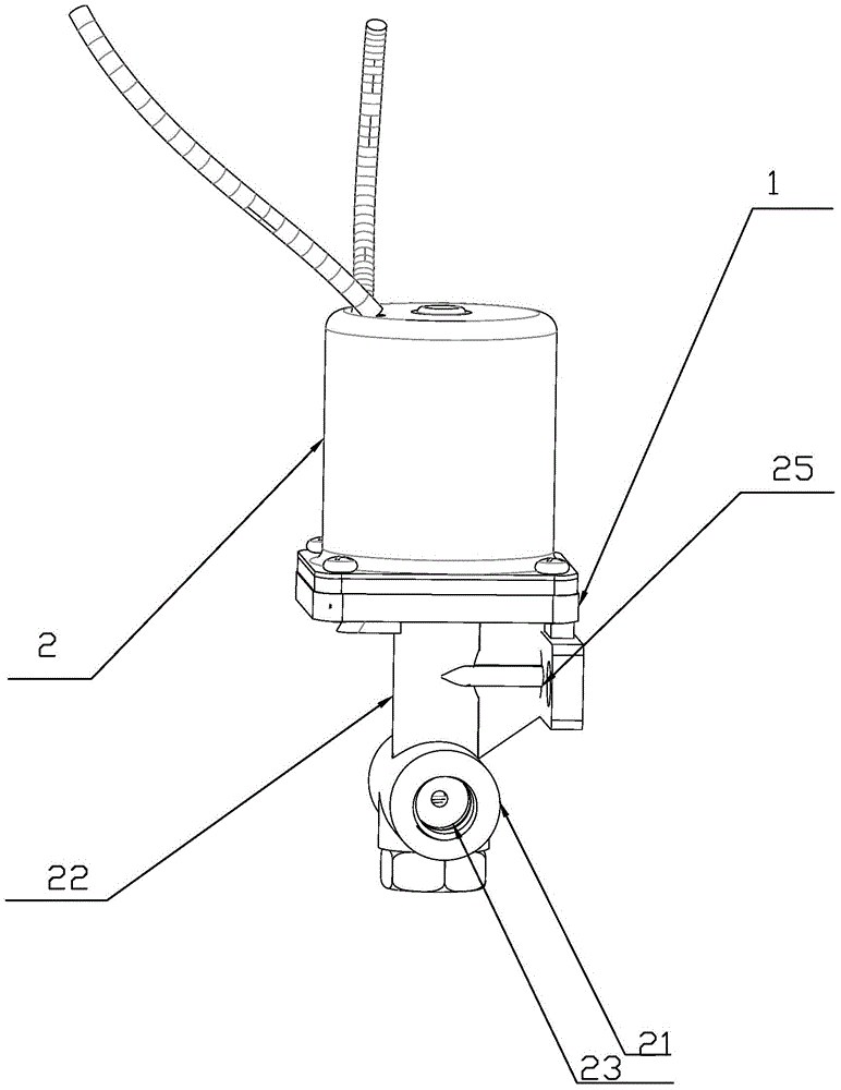
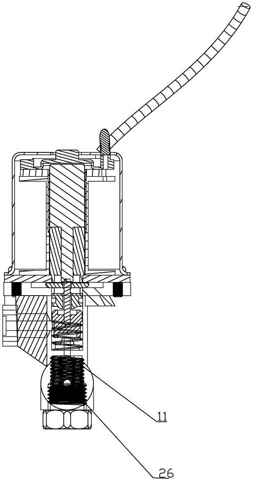
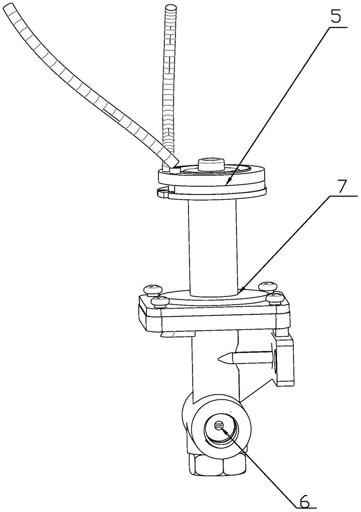
[0025] Such as figure 1 figure 2 Figure 4 Figure 6 As shown, the electromagnetic gas valve includes a valve body (1) and a casing (2) that is movably connected with the valve body (1) above the valve body (1). The inside of the casing (2) is hollowed out to form a first cavity. Electromagnetic components are arranged in the cavity, and the electromagnetic components include a moving iron core (3), a static iron core (4) and an electric drive unit (5). The electric drive unit (5) is a common electric power generating device similar to a motor. The body (1) is provided with a number of inlet holes (6) for the gas to enter the valve body (1), the valve body (1) and the shell (2) are connected with a socket (7), and the static iron core (4) Fixed in the second cavity, a moving iron core (3) is arranged at intervals above the static iron core (4) in the second cavity, and the static iron core (4) is provided with a through hole (8). One end of the iron core (3) is connected ...


PUM


Abstract

The invention relates to an electromagnetic gas valve comprising a valve body and a shell. An electromagnetic component is arranged in the shell and comprises a movable core, a static core and an electric drive unit, a plurality of air inlets allowing gas to enter the valve body are arranged in the valve body, an insertion opening is arranged in the joint of the valve body and the shell, a second cavity is formed by downwards extending in the valve body along the direction of the insertion opening, the static core is fixedly arranged in the second cavity, one movable core is arranged in the second cavity and above the static core at a distance from the static core, the static core is provided with a through hole, a connecting shaft which can be matched with the through hole is arranged in a first cavity, the connecting shaft is connected with the movable core fixedly and connected with the static core movably, a gas baffle block is arranged at the bottom of the connecting shaft, a gas pipeline is arranged inside the valve body and below the gas baffle block, and the spacing distance between the gas baffle block and the gas pipeline is smaller than that between the movable core and the static core. After the gas baffle block is arranged, the gas baffle block are controlled to ascend and descend by vertical ascending and descending of the movable core and the static core under electromagnetic induction so as to cover the gas pipeline.

Description

technical field [0001] The invention relates to the field of valves, in particular to an electromagnetic air valve with large air output, simple structure and better sealing performance. Background technique [0002] Solenoid gas valve is a kind of solenoid valve whose medium is gas through the valve body. The solenoid valve usually includes a valve body, an air inlet, a moving iron core arranged in the valve body and a static iron core opposite to the moving iron core, a coil, and a ventilation pipe is usually provided at the contact between the static iron core and the moving iron core. The principle is usually that when the electromagnetic valve is not energized, a spring is used between the moving iron core and the static iron core to bounce them apart. When the gas enters the valve body through the air inlet hole, it will pass through the ventilation pipe on the static iron core. The gas flowing out of the ventilation pipe controls some pneumatic components. When the e...

Claims


Application Information

Patent Timeline
IPC IPC(8): F16K31/06
CPCF16K27/029F16K31/0655F16K31/0675
Inventor 林明坚
Owner 瑞安市洛伊德机车部件有限公司
Why Eureka
Try Eureka