
Separate floating cover type novel methane fermentation device

A biogas fermentation, a new type of technology, applied in biochemical cleaning equipment, enzymology/microbiology equipment, bioreactor/fermentation tank combination, etc., can solve the problems of reducing gas production, difficult stirring, and inconvenient discharge of biogas tanks, etc. Achieve the effect of improving fermentation efficiency and increasing biogas output

Inactive Publication Date: 2018-03-20
CHONGQING UNIV OF ARTS & SCI
View PDF0 Cites 0 Cited by
  • Summary
  • Abstract
  • Description
  • Claims
  • Application Information

AI Technical Summary

Problems solved by technology

[0002] The traditional agricultural biogas fermentation device has four disadvantages: First, it is difficult to stir in the fermentation room. Over time, the old slag in the tank cannot be discharged circularly, resulting in an open circuit of the fermentation material in and out, and the sustainable imbalance of microbial metabolic activities, which affects the full fermentation of raw materials. , which reduces the gas production; second, the performance of the biogas fermentation process is significantly affected by the operating temperature, and the gas production may stop when it is lower than 10°C; third, the traditional agricultural biogas digesters are generally buried underground, which makes it extremely inconvenient to discharge the biogas digester and affects the biogas digester. Daily operation and management; Fourth, traditional biogas digesters need to interrupt the fermentation process to achieve large discharge, which affects the continuity of gas production
Based on the above reasons, the popularization of agricultural biogas fermentation equipment has been greatly restricted

Method used


Image

  • Separate floating cover type novel methane fermentation device
  • Separate floating cover type novel methane fermentation device

Examples


Embodiment Construction

[0017] The present invention will be further described below in conjunction with accompanying drawing.

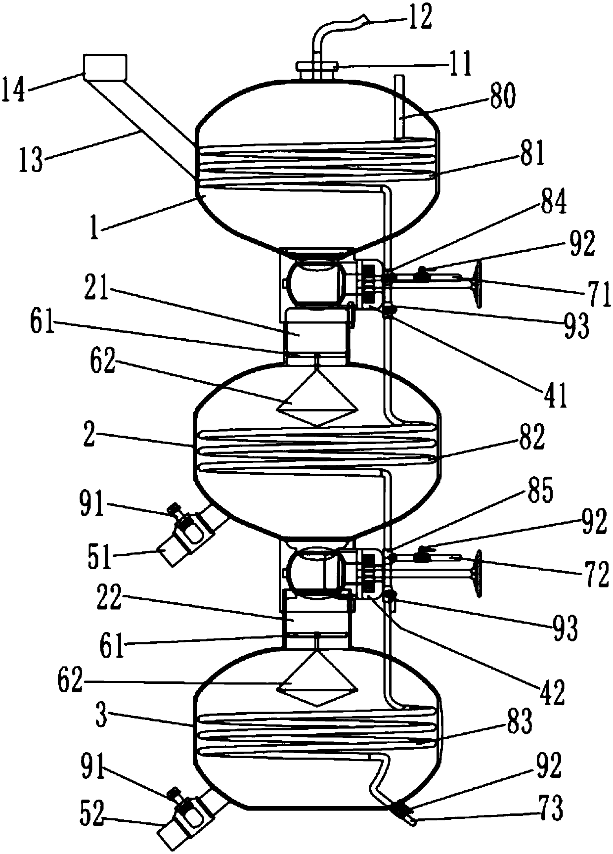
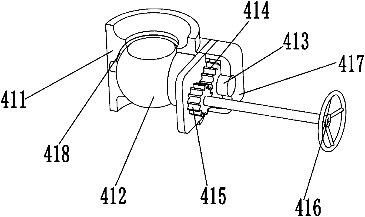
[0018] Such as figure 1 with figure 2 As shown, the present invention is composed of the first fermentation room 1, the second fermentation room 2 and the third fermentation room 3 etc. which are sequentially connected from top to bottom. A movable top cover 11 is provided on the first fermentation room 1. The movable top cover 11 is pierced with an air duct 12, and one side of the first fermentation room 1 is provided with a steam input pipe 80 pierced in, and the other side is connected with a feed pipe 13, and the feed pipe 13 is also connected with the feed room 14, the second fermentation room 2 is provided with a first discharge pipe 51, and the third fermentation room 3 is provided with a second discharge pipe 52.

[0019] A first connecting pipe 21 is provided between the first fermentation room 1 and the second fermentation room 2, a second connecting pipe 22 is...


PUM


Abstract

The invention discloses a novel biogas fermentation device of separation floating cover type, which comprises a first fermentation room (1), a second fermentation room (2) and a third fermentation room (3) which are sequentially connected from top to bottom. A fermentation room (1) is provided with a steam input pipe (80), a valve is provided between two adjacent fermentation rooms, and a valve is provided in the second fermentation room (2) and the third fermentation room (3). There is a diffusion device; the three fermentation rooms are equipped with annular air pipes, and each of the annular air pipes passes through the corresponding fermentation room, and the annular air pipes between two adjacent fermentation rooms protrude The ends are connected to each other, and the corresponding steam pipes are externally connected to the connected positions. The present invention is provided with three fermentation rooms connected from top to bottom, and is equipped with a diffusion device, and an annular air pipe connected to a steam conduit, while controlling the temperature, it can also discharge materials in a timely manner without affecting the continuity of fermentation. The fermentation efficiency is improved, and the output of biogas is increased.

Description

technical field [0001] The invention relates to the technical field of biogas fermentation, in particular to a novel biogas fermentation device of separation floating cover type. Background technique [0002] The traditional agricultural biogas fermentation device has four disadvantages: First, it is difficult to stir in the fermentation room. Over time, the old slag in the tank cannot be discharged circularly, forming a broken circuit of the fermentation material in and out, and the sustainable imbalance of microbial metabolic activities, which affects the full fermentation of raw materials. , which reduces the gas production; second, the performance of the biogas fermentation process is significantly affected by the operating temperature, and the gas production may stop when it is lower than 10°C; third, the traditional agricultural biogas digesters are generally buried underground, which makes it extremely inconvenient to discharge the biogas digester and affects the bioga...

Claims


Application Information

Patent Timeline
IPC IPC(8): C12M1/38C12M1/107C12M1/04C12M1/00
CPCC12M21/04C12M23/58C12M29/06C12M37/04C12M41/12
Inventor 彭万勇
Owner CHONGQING UNIV OF ARTS & SCI
Learn More