Cloth drying device

A technology for drying cloth and drying rollers, applied in printing, printing machines, general parts of printing machinery, etc., can solve problems such as waste of heat source, and achieve the effects of increasing circulation, increasing air output, and increasing gaps

Inactive Publication Date: 2021-09-24
许凤仙
View PDF0 Cites 0 Cited by
  • Summary
  • Abstract
  • Description
  • Claims
  • Application Information

AI Technical Summary

Problems solved by technology

In addition, the existing drying rollers are in direct contact with the surface of the fabric, and dry hot air is also discharged from the surrounding side where no fabric passes, which is easy to cause waste of heat sources.

Method used


Image

  • Cloth drying device
  • Cloth drying device
  • Cloth drying device

Examples


Embodiment Construction

[0027] The following will clearly and completely describe the technical solutions in the embodiments of the present invention with reference to the accompanying drawings in the embodiments of the present invention. Obviously, the described embodiments are only some, not all, embodiments of the present invention. Based on the embodiments of the present invention, all other embodiments obtained by persons of ordinary skill in the art without creative efforts fall within the protection scope of the present invention.

[0028] In describing the present invention, it is to be understood that the terms "opening", "upper", "lower", "thickness", "top", "middle", "length", "inner", "surrounding" etc. Indicating orientation or positional relationship is only for the convenience of describing the present invention and simplifying the description, and does not indicate or imply that the components or elements referred to must have a specific orientation, be constructed and operated in a sp...


PUM


Abstract

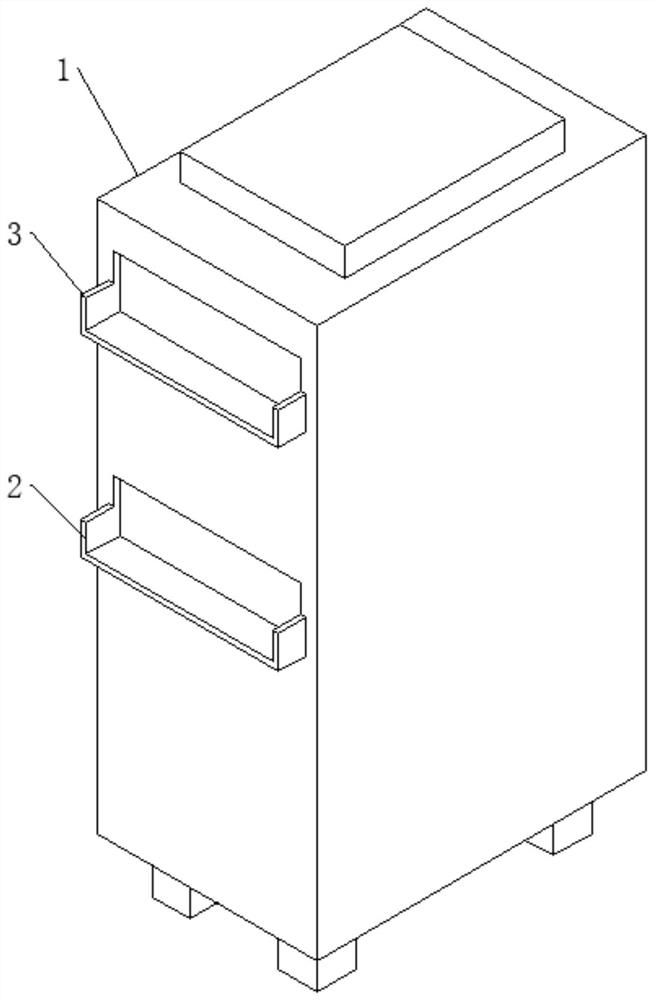
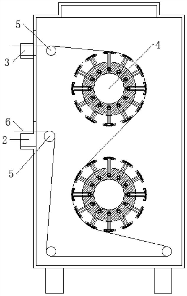
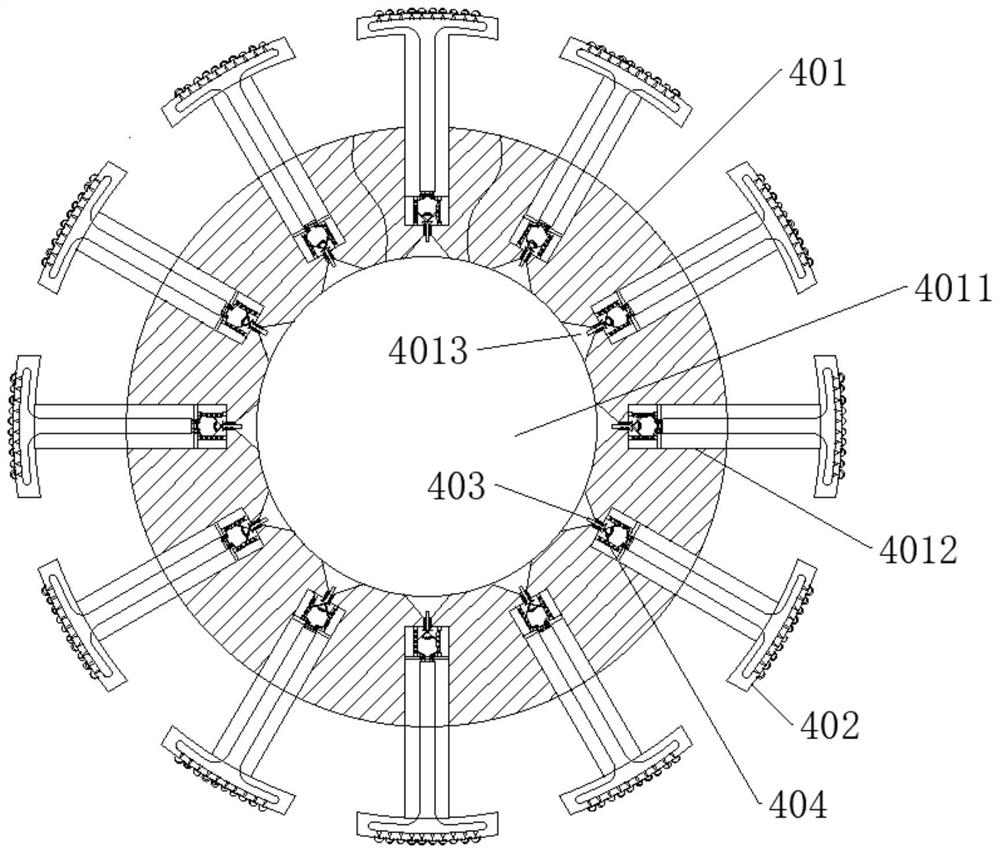
The invention discloses a cloth drying device, and relates to the technical field of cloth printing devices. The cloth drying device comprises a box body, a feeding port and a discharging port are formed in the box body, and guide rollers are installed on the inner side of the feeding port and the inner side of the discharging port; at least one drying roller is rotationally installed in the box body, and cloth to be dried passes through the surface of the drying roller. According to the cloth drying device, dry hot air is discharged from inside to outside through the drying rollers, moisture on cloth is taken away, the purpose of rapid drying is achieved, in addition, the cloth is dried in the box body, the temperature and humidity in the box body are convenient to control, and accurate drying is achieved.

Description

technical field [0001] The invention belongs to the technical field of cloth printing devices, in particular to a cloth drying device. Background technique [0002] After the fabric is printed, it needs to be dried and shaped by the drying equipment. Most of the existing drying equipment utilizes a box structure. The box is equipped with an air inlet and an air outlet. The box is equipped with a corresponding cloth guide roller, a heating pipe, and a blower, so that the hot air is used to dry the cloth in the box. . However, since the fabric is not dry, the wind force needs to be controlled at a suitable strength, not too large or too small, and the temperature of the heating tube should not be too high, otherwise it will easily cause deformation and damage of the fabric, which will affect the subsequent use of the fabric. At the same time, due to the blowing operation, the heat distribution in the wind direction is not uniform, and it is easy to cause uneven heating and d...

Claims


Application Information

Patent Timeline
Patent Type & Authority Applications(China)
IPC IPC(8): B41F23/04
CPCB41F23/04
Inventor 许凤仙
Owner 许凤仙
Why Eureka
Try Eureka