Cooling substrate of micro heat pipe

A technology of heat dissipation substrate and micro heat pipe, applied in cooling/ventilation/heating transformation, electrical components, electric solid-state devices, etc., can solve the problems of unfavorable integration and miniaturization, increase design complexity, increase extra cost, etc., and achieve no maintenance. , High heat dissipation efficiency, temperature controllable effect

Inactive Publication Date: 2008-05-07
SUN YAT SEN UNIV
View PDF0 Cites 24 Cited by
  • Summary
  • Abstract
  • Description
  • Claims
  • Application Information

AI Technical Summary

Problems solved by technology

Traditional temperature control technology generally uses temperature detection and feedback circuit control, which is complex, not conducive to integration and miniaturization, and at the same time increases additional costs and design complexity.

Method used


Image

  • Cooling substrate of micro heat pipe
  • Cooling substrate of micro heat pipe
  • Cooling substrate of micro heat pipe

Examples


Embodiment Construction

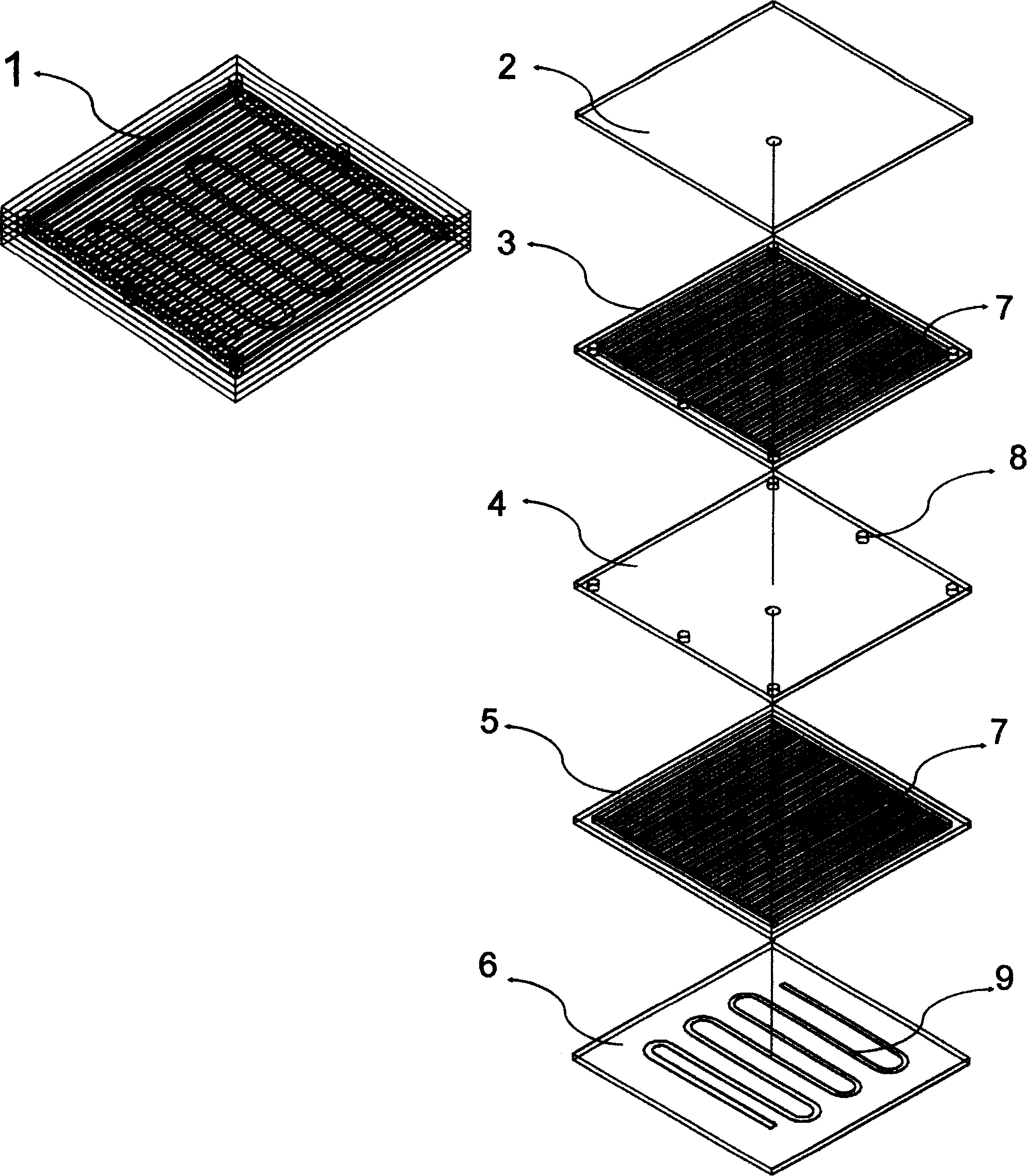
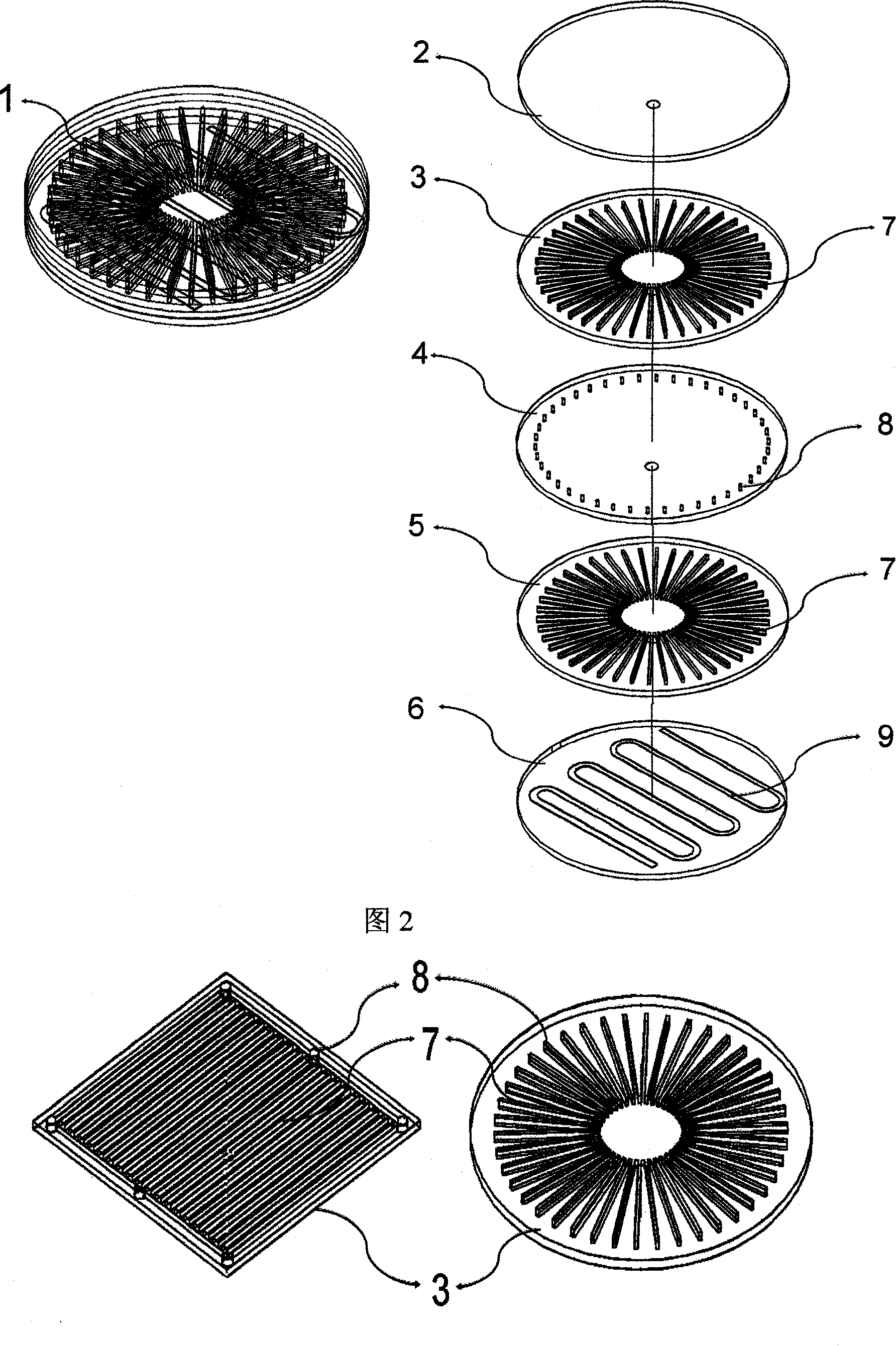
[0023] figure 1 Among them, the left figure is a schematic diagram of the entire micro heat pipe heat dissipation substrate 1 , and the right figure is a structure diagram of each layer of the micro heat pipe heat dissipation substrate 1 . The heat dissipation substrate 1 of the micro heat pipe is composed of 5 layers, and the top ceramic layer 2 is a ceramic sheet with high thermal conductivity, which can be made into a cup and bowl shape required for circuit or LED packaging. The second layer is a ceramic sheet (or metal sheet) heat dissipation layer 3 with a micro-heat pipe structure array, on which there is a rectangular micro-heat pipe 7 structure array, and its edge forms a passage with the lower micro-heat pipe through a communication pipe 8. The third layer is a heat-insulating ceramic layer 4, the purpose of which is to form a hot end and a cold end of the upper and lower layers of micro-heat pipe cooling layers, and its internal communication pipe 8 enables the upper...


PUM


Abstract

The present invention relates to an electronic component radiating substrate, in particular to a micro heat pipe radiating substrate. The micro heat pipe radiating substrate is formed by a plurality of layers of flat plate radiating layer. A micro heat pipe structure is manufactured in an upper radiating layer and a lower radiating layer to be provided with a hot end and a cold end in vertical direction. A temperature control ceramic layer at the bottom is used for controlling the temperature of the cold end, so the whole substrate is provide with radiating and temperature control functions. Compared with the traditional metal (or ceramic) substrate, the substrate adopts the design of the micro heat pipe structure and the cold end temperature control. So the present invention not only is characterized by strong heat transport capacity, good radiating and soaking, but also is capable of controlling the temperature of the substrate. The novel substrate is used in the electron field of semiconductor light emitting diode, semiconductor laser device, semiconductor component, integrated circuit and CPU and so on and is of advantages.

Description

technical field [0001] The invention relates to a heat dissipation substrate of an electronic component, in particular to a heat dissipation substrate of a micro heat pipe. Background technique [0002] There are two major trends in the development of electronics and related industries. One is the pursuit of miniaturization and integration, and the other is the pursuit of high frequency and high computing speed, which leads to a significant increase in the heat generation per unit volume of electronic components. In fact, the heat dissipation problem of electronic equipment has become a bottleneck restricting the development of the microelectronics industry. Investigate the cooling problem of modern electronic equipment, generally divided into three levels, the first level: heat transfer from the chip to the substrate, the substrate material is usually plastic, metal and ceramics; the second level: heat transfer from the substrate to the cooling plate; the third level Layer...

Claims


Application Information

Patent Timeline
Patent Type & Authority Applications(China)
IPC IPC(8): H05K7/20H01L23/427
CPCH01L2224/45144H01L2224/48091H01L2224/48227H01L2924/1461
Inventor 王钢范冰丰
Owner SUN YAT SEN UNIV
Why Eureka
Try Eureka