Electromagnetic valve with fluid flow regulation function

A fluid flow and solenoid valve technology, applied in the field of solenoid valves, can solve problems such as the inability to adjust and control fluid flow in real time, and achieve the effects of high flow regulation stability and reasonable structure settings

Active Publication Date: 2014-11-19
江苏荣威阀门有限公司
View PDF5 Cites 5 Cited by
  • Summary
  • Abstract
  • Description
  • Claims
  • Application Information

AI Technical Summary

Problems solved by technology

This structural setting of the existing solenoid valve can only realize simple opening and closing functions, and cannot automatically adjust and control the fluid flow in real time as required, so there is still a lot of room for improvement to the existing structure and technology

Method used


Image

  • Electromagnetic valve with fluid flow regulation function
  • Electromagnetic valve with fluid flow regulation function
  • Electromagnetic valve with fluid flow regulation function

Examples


Embodiment 1

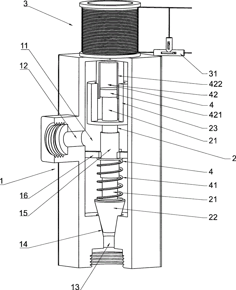
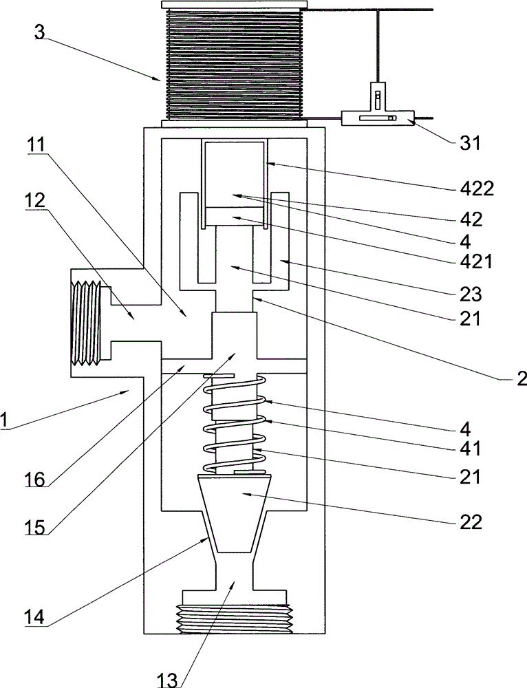
[0029] Such as figure 1 with figure 2 As shown, the solenoid valve with fluid flow regulating function according to the present invention includes a casing 1 and a core body 2. The casing 1 is provided with an inner cavity 11, and the core body 2 is arranged in the inner cavity so that it can move up and down. In the cavity 11, the above two components constitute the main structure of the present invention. It should be noted that, in order to facilitate the installation of the core body 2, the shell 1 can be formed by butting the left and right shells or the upper and lower shells, and of course a combination of multiple shells is not excluded.

[0030] The housing 1 is provided with a first port 12 , a second port 13 and a valve port 14 , the first port 12 communicates with the inner cavity 11 , and the second port 13 communicates with the inner cavity 11 through the valve port 14 . It should be noted that the first port 12 can be provided in multiples, forming a many-to-...

Embodiment 2

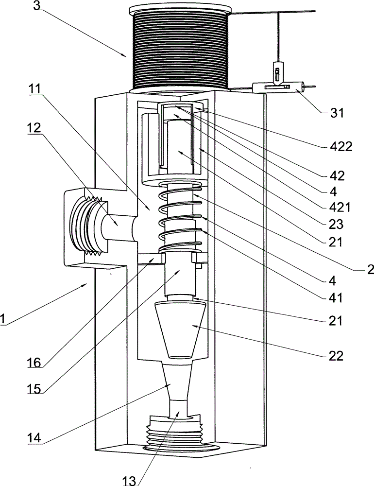
[0039] Such as image 3with Figure 4 As shown, the electromagnet 3 produces a repelling force on the magnetizer 23, and the direction is downward. The piston 421 is arranged at the bottom of the cylinder shell 422. The rebound force is due to the thin gas in the cylinder shell 422 after the piston 421 is pulled. The piston 421 is generated by the fluid outside the cylinder shell 422 or the atmospheric pressure. Of course, a fully sealed cylinder shell 422 can also be used. At this time, the rebound force is generated by the piston 421 reversely compressing the gas in the cylinder shell 422. The rebound force The direction is upward; the spring 41 is a compression spring, which is sleeved outside the pillar 21, and one end is supported by the support member 16, and the other end is supported by the magnetizer 23. The rebound force is generated by the compression of the spring 41, and the direction is upward.

[0040] The working principle of this embodiment is that after the ...


PUM


Abstract

The invention relates to the technical field of electromagnetic valves, in particular to an electromagnetic valve with a fluid flow regulation function. The electromagnetic valve comprises a shell and a core. An inner cavity is formed inside the shell. The shell is provided with a first port, a second port and a valve opening. The first port is communicated with the inner cavity. The second port is communicated with the inner cavity through the valve opening. The core is arranged in the inner cavity in the mode that the core can move up and down. The core is composed of a supporting column and a valve arranged at the lower end of the supporting column. The valve is arranged corresponding to the valve opening. A magnetizer is arranged on the supporting column. An electromagnet is arranged on the shell and is arranged corresponding to the magnetizer. A current control device used for regulating the magnitude of current or voltage is arranged on a circuit loop of the electromagnet. An elastic force balancing device is arranged in the inner cavity. The electromagnetic valve has the advantages of being capable of automatically regulating fluid flow in real time according to requirements, reasonable in structural arrangement, high in stability and the like.

Description

technical field [0001] The invention relates to the technical field of solenoid valves, in particular to a solenoid valve with the function of regulating fluid flow. Background technique [0002] Solenoid valves are commonly used automatic control components in industrial control systems, and are used for opening and closing control of pipelines in fluid transportation. The existing solenoid valve generally consists of a housing, an electromagnet on the housing, a moving magnet and a static magnet in the housing, connecting rods, springs and other components. The electromagnet drives the connecting rod to move quickly by turning on and off the power. To realize the opening and closing of the solenoid valve. This structural setting of the existing solenoid valve can only realize simple opening and closing functions, and cannot automatically adjust and control the fluid flow in real time as required, so there is still a lot of room for improvement to the existing structure an...

Claims


Application Information

Patent Timeline
Patent Type & Authority Applications(China)
IPC IPC(8): F16K31/06F16K1/52
CPCF16K31/0655F16K1/52F16K31/0675F16K31/0686
Inventor 戴佩裕
Owner 江苏荣威阀门有限公司
Why Eureka
Try Eureka