Supercharge Your Innovation With Domain-Expert AI Agents!

Camera mount capable of multi-angle rotation

A camera and multi-angle technology, applied in the field of cameras, can solve the problems of unstable installation, easy loosening, inability to meet camera installation and video recording, etc., and achieve the effect of being firmly fixed on the wall and easy to use

Active Publication Date: 2016-03-23
JING LIN CHENGDU SCI & TECH
View PDF5 Cites 0 Cited by
  • Summary
  • Abstract
  • Description
  • Claims
  • Application Information

AI Technical Summary

Problems solved by technology

Usually, the camera must be installed on the wall with the help of a mounting frame, but the current mounting frame is not installed firmly and is easy to loosen, and the part of the mounting frame used to install the camera cannot be rotated horizontally and vertically at the same time, allowing the camera to achieve any Angle installation, especially unable to meet the installation and recording of cameras in special-shaped corners in some public places

Method used


Image

  • Camera mount capable of multi-angle rotation

Examples


Embodiment 1

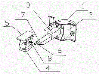
[0020] Such as figure 1 As shown, the present invention includes a U-shaped bolt 1, a mounting plate 2, a telescopic rod 3 capable of telescopic front and back, a mounting base 4, a top cover 5, a rotating fastener 6 and a fastening bolt 8, and the two ends of the U-shaped bolt 1 are vertical Crossing the mounting plate 2; the top of the mounting seat 4 is connected to the top cover 5 by fastening bolts 8, and a bracket is also provided on one side of the mounting seat 4 to connect with the rotating fastener 6; one end of the telescopic rod 3 is connected by a bolt Vertically fixed on the vertical mounting plate 2, a square groove 7 is provided on the other end surface; the rotating fastener 6 is hollow, and one side of the square groove 7 is located in the cavity of the rotating fastener 6.

[0021] When it is practical, just install the camera on the mounting base and fix it with bolts, and fix the mounting plate on the wall with U-shaped bolts, then adjust the length of the...

Embodiment 2

[0023] The preferred specific structure of this embodiment on the basis of Embodiment 1 is as follows: the rotating fastener 6 can be rotated arbitrarily from 0° to 360° around the side of the cavity of the rotating fastener 6 . It can ensure that the mounting frame can reach any angle, and it is convenient to install the camera and the camera for monitoring and collection.

Embodiment 3

[0025] The preferred specific structure of this embodiment is as follows on the basis of the above embodiments: the top cover 5 can rotate around the fastening bolt 8 . According to the shape of the installed camera and the rotating position of the camera, the position of the top cover can be adjusted so that it can cover the top of the camera and prevent dust from falling on the camera.

[0026] Described telescoping link 3 is vertically installed on the front of the square plate of mounting plate 2 central positions, also connects V-shaped plate on both sides of square plate, and the two ends of U-shaped bolt 1 pass through from corresponding V-shaped plate back side respectively. The setting of the V-shaped board can better fit the corners such as the corner of the wall, and the installation on the wall is more secure. The telescopic rod 3 comprises two overlapping cuboids that can slide mutually. It is more convenient to expand and contract, and better realize the purpose...


PUM


Abstract

The invention discloses a camera mounting rack with a multi-angle rotating function. The camera mounting rack comprises a U-shaped bolt, a mounting plate, a telescopic rod which can telescope forwards and backwards, a mounting seat, a top cover, a rotary fastener and fastening bolt. Two ends of the U-shaped bolt vertically transversely penetrate the mounting plate. The top of the mounting seat is connected with the top cover through the fastening bolt. One side of the mounting seat is provided with a support connected with the rotary fastener. One end of the telescopic rod is vertically fixed on the vertical mounting plate through bolts. The other end face of the telescopic rod is provided with a square groove. The rotary fastener is hollow. One lateral side of the square groove is located in the cavity of the rotary fastener. By the structure, the camera mounting rack has the advantages that the mounting rack is less prone to loosening when being mounted on a wall, and the mounting rack can rotate transversely and longitudinally and is safe and convenient to use and especially suitable for mounting a camera at special-shaped corners.

Description

technical field [0001] The invention relates to the field of cameras, in particular to a camera installation frame capable of realizing multi-angle rotation. Background technique [0002] Camera (CAMERA), also known as computer camera, computer eye, electronic eye, etc., is a video input device that is widely used in video conferencing, telemedicine and real-time monitoring. Ordinary people can also talk and communicate with each other through the network with images and sounds through the camera. In addition, people can also use it for various popular digital images and audio-visual processing. Cameras are most commonly used in the field of real-time monitoring, and cameras are often installed in hidden places such as corners to avoid being discovered. Usually, the camera must be installed on the wall with the help of a mounting frame, but the current mounting frame is not installed firmly and is easy to loosen, and the part of the mounting frame used to install the camer...

Claims


Application Information

Patent Timeline
Patent Type & Authority Patents(China)
IPC IPC(8): F16M13/02F16M11/12F16M11/18
Inventor 曾衡东殷刚
Owner JING LIN CHENGDU SCI & TECH
Features
  • R&D
  • Intellectual Property
  • Life Sciences
  • Materials
  • Tech Scout
  • Unparalleled Data Quality
  • Higher Quality Content
  • 60% Fewer Hallucinations
Learn More