Cable tube type stranding device for hardware alternating current equipment processing

A technology of alternating current and equipment, applied in cable/conductor manufacturing, circuits, electrical components, etc., can solve the problems of easy loosening of cables, inability to adjust the tightness of cable strands, affecting people's normal use, etc., to improve the effect of stranding Effect

Inactive Publication Date: 2020-08-28
烟台中连智能科技有限公司
View PDF0 Cites 4 Cited by
  • Summary
  • Abstract
  • Description
  • Claims
  • Application Information

AI Technical Summary

Problems solved by technology

In the production process of cables, people need to twist the cables, but the traditional twisting device cannot adjust the tightness of t

Method used


Image

  • Cable tube type stranding device for hardware alternating current equipment processing
  • Cable tube type stranding device for hardware alternating current equipment processing
  • Cable tube type stranding device for hardware alternating current equipment processing

Examples


Embodiment 1

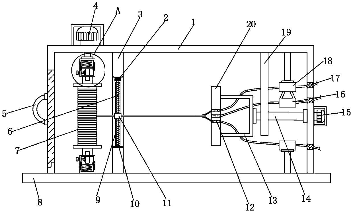
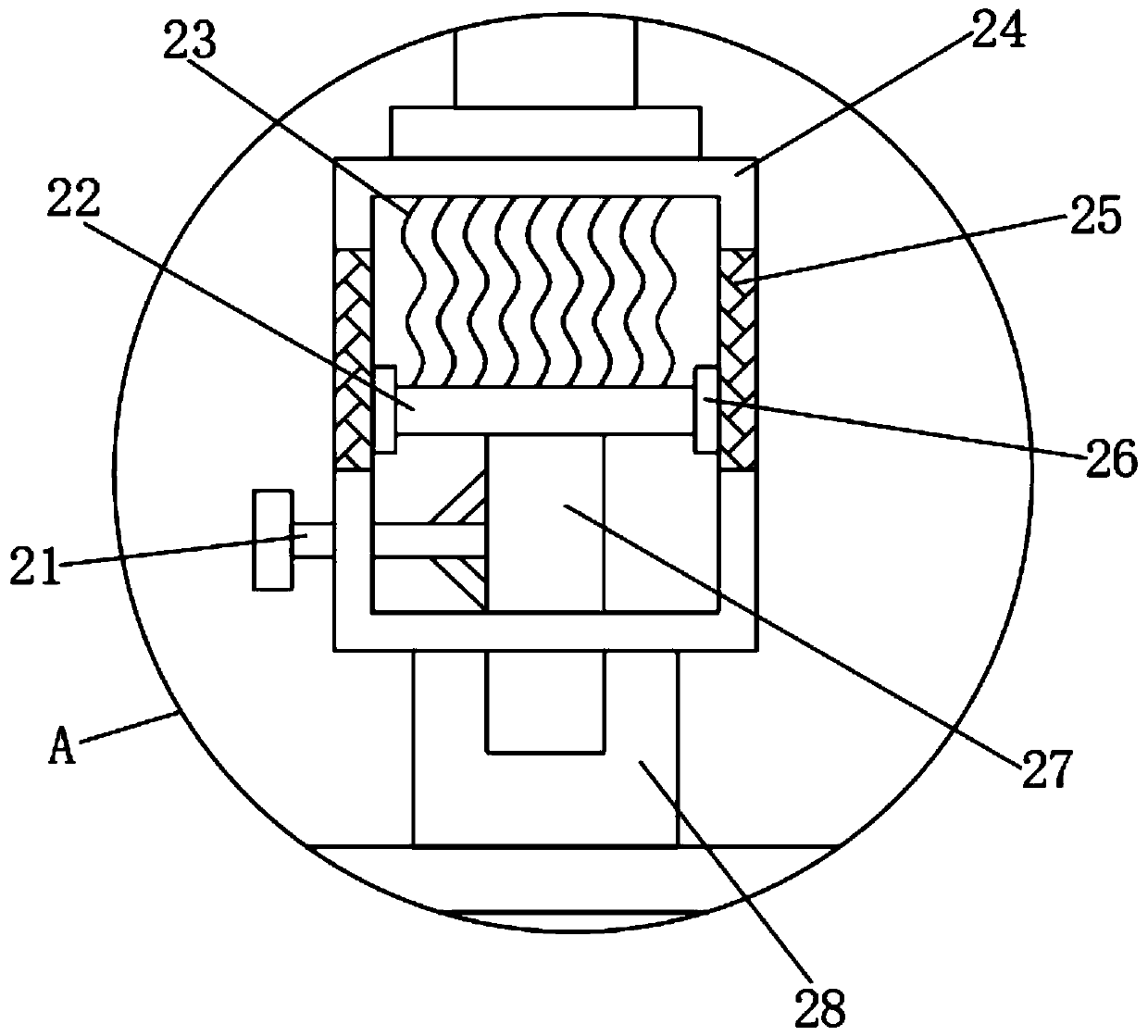
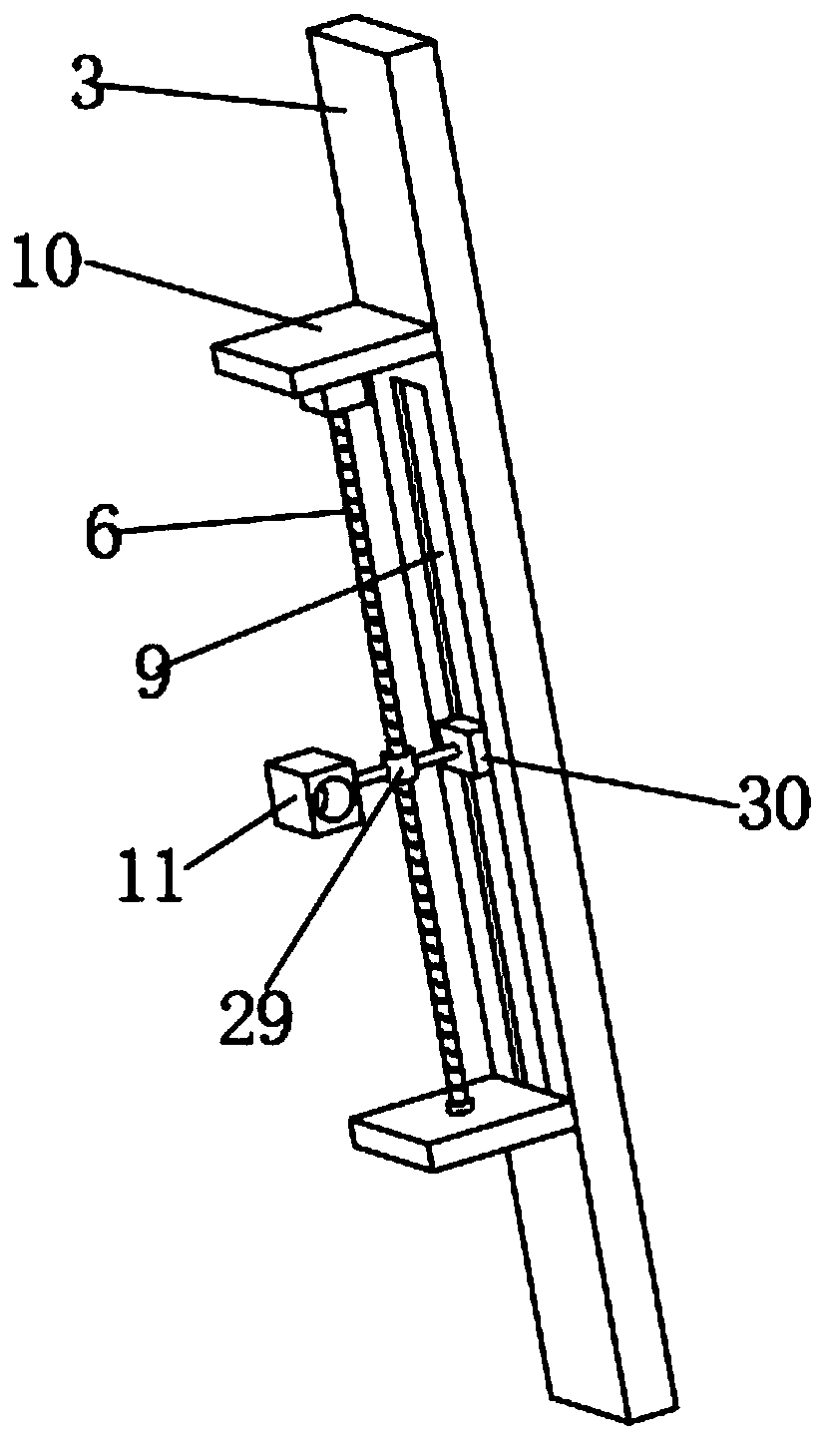
[0031] refer to Figure 1-3 , a cable tube type twisting device for Wujinjiaodian equipment processing, including a box body 1, a second motor 4 is connected to the top outer wall of the box body 1 by bolts, and the outer wall of one end of the output shaft of the second motor 4 is connected by bolts. Sleeve 24, one side inner wall of sleeve 24 is welded with spring 23, and the outer wall of one end of spring 23 is welded with connection disc 22, and the outer wall of both sides of connection disc 22 is all connected with second slide block 26 by bolt, and connection disc 22 One side of the outer wall of the card column 27 is connected with a clamping post 27 by bolts, and one side of the card post 27 is connected with a handle 21 by bolts, and one end of the clamping post 27 is clamped with a fixing seat 28, and one side of the fixing seat 28 The outer wall is connected with a Take-up roller 7, one side outer wall of box body 1 is connected with third motor 15 by bolt, and on...

Embodiment 2

[0035] refer to Figure 4-5 , a cable tube type stranding device for Wujinjiaodian equipment processing. Compared with Embodiment 1, the outer wall of one side of the twisting reel 20 is connected with a fixing plate by bolts, and the bottom outer wall of the fixing plate is connected by bolts. There is an electric push rod 31, the outer wall of one end of the electric push rod 31 is connected with a fixed plate by bolts, and the outer wall of one end of the fixed plate is connected with a snap ring 32 by bolts.

[0036] Working principle: when in use, when people twist the cable body 33, people pass a plurality of cables through the through slot 12, and when the cables pass through the through slot 12, people start the third motor 15, and the third The motor 15 drives the twisting reel 20 to rotate, so that the twisting work of the cable can be completed. At the same time, people can start the electric push rod 31 when the cable is twisted, and the electric push rod 31 drives...


PUM


Abstract

The invention discloses a cable tube type stranding device for hardware alternating current equipment processing. The device comprises a box body, wherein a second motor is arranged on the outer wallof the top of the box body, a bush is arranged on the outer wall of one end of the output shaft of the second motor, a spring is arranged on the inner wall of one side of the bush, a connecting disc is arranged on the outer wall of one end of the spring, second sliding blocks are arranged on the outer walls of the two sides of the connecting disc, and a clamping column is arranged on the outer wall of the one side of the connecting disc. According to the invention, when people strand cables, a plurality of cables penetrate through a through groove, a second motor is started after the cables penetrates through the through groove, and the second motor drives a stranding disc to rotate, so that stranding work of the cables can be completed; and people can start an electric push rod when stranding the cables, and the electric push rod drives a clamping ring to move, so that the multiple cables can be close, the stranding effect of the multiple cables is improved, and the situation that thecables are loosened after being stranded is avoided.

Description

technical field [0001] The invention relates to the technical field of cable stranding, in particular to a cable tube type stranding device for processing Wujinjiaodian equipment. Background technique [0002] The cable is usually a rope-like cable twisted by several or several groups of conductors (at least two in each group). Each group of conductors is insulated from each other and is often twisted around a center. Insulating covering. Most of them are erected in the air or installed underground or underwater for telecommunications or power transmission. [0003] The stranded wire is realized by the rotation of the twisted single wire around the stranded wire shaft at an equal angular velocity and the uniform forward movement of the stranded wire. Commonly used are copper and aluminum. Copper and aluminum wires can be twisted into conductor batteries of various cross-sections and different types of wires and cables. In the production process of cables, people need to t...

Claims


Application Information

Patent Timeline
IPC IPC(8): H01B13/02
CPCH01B13/02
Inventor 慕长福
Owner 烟台中连智能科技有限公司
Why Eureka
Try Eureka