Real object exhibition platform convenient for 360-degree full-angle shooting

A kind of physical booth and full-angle technology, which is applied in image communication, teaching aids for electric operation, parts and components of color TV, etc., can solve the problems of complex viewing angle of camera, achieve low cost, low failure rate, and simple effect

Active Publication Date: 2014-11-19
STATE GRID CORP OF CHINA +1
View PDF6 Cites 1 Cited by
  • Summary
  • Abstract
  • Description
  • Claims
  • Application Information

AI Technical Summary

Problems solved by technology

[0003] The purpose of the present invention is to solve the problem of fixing the camera on the top of the booth or at a certain fixed angle in the existing camera physical exhibition stand, and changing the observation angle of the camera is complicated; the present invention provides a device that facilitates 360-degree full-angle photography

Method used


Image

  • Real object exhibition platform convenient for 360-degree full-angle shooting

Examples


specific Embodiment approach 1

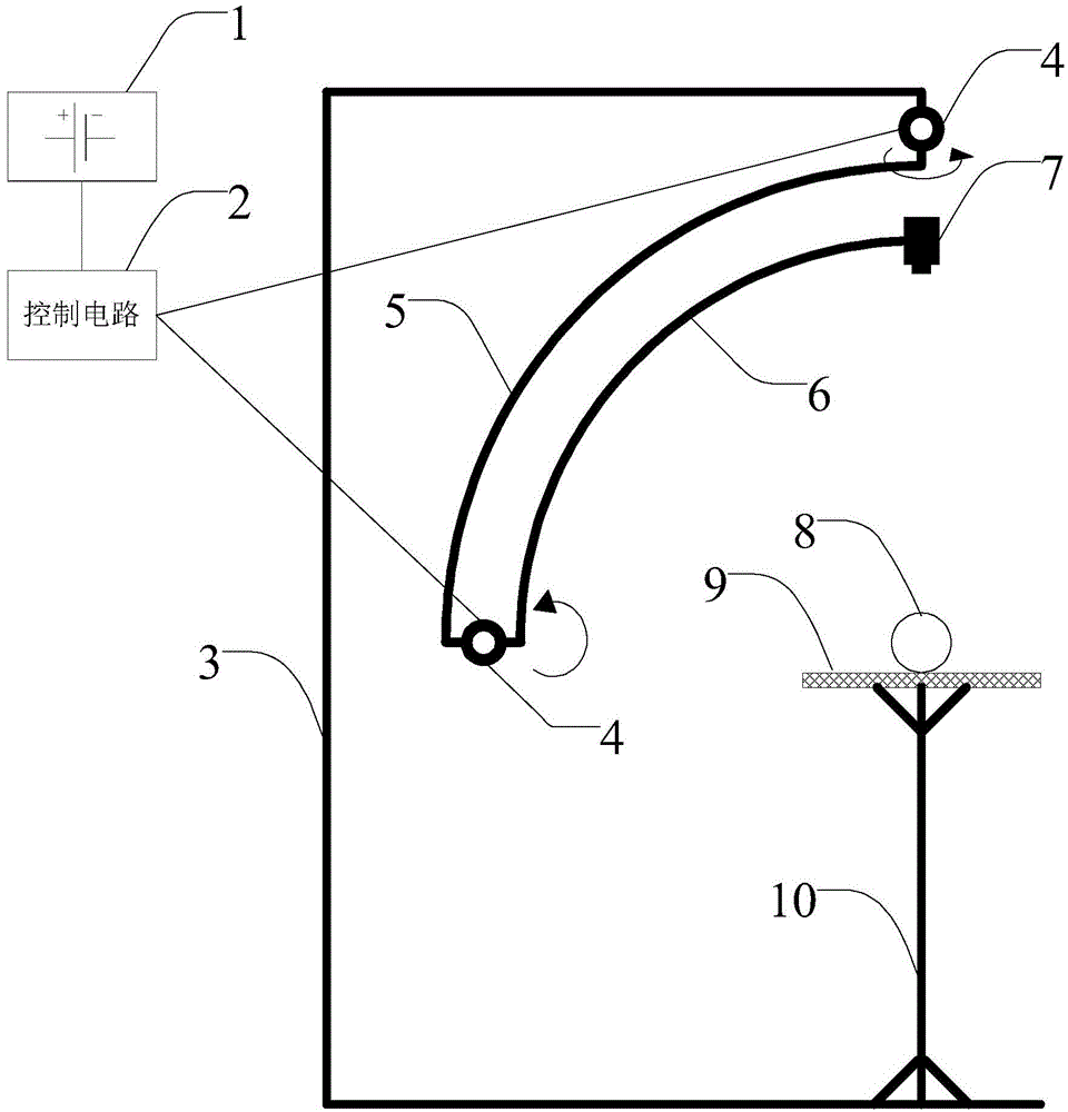
[0012] Specific implementation mode one: see figure 1 Describe this embodiment, a device that is convenient for 360-degree full-angle photography described in this embodiment, it includes a power supply 1, a control circuit 2, a fixed arm 3, two steering gears 4, a horizontal rotating arm 5, a vertical rotating Support arm 6, camera 7 and physical booth;

[0013] A steering gear 4 is hoisted on the fixed support arm 3, and the steering gear 4 is rotationally connected with one end of the horizontal rotating support arm 5,

[0014] The other end of the horizontal rotation support arm 5 is fixedly connected with another steering gear 4, and the other steering gear 4 is rotationally connected with one end of the vertical rotation support arm 6, and the other end of the vertical rotation support arm 6 is fixed with a camera 7;

[0015] The power supply 1 is used to provide the operating voltage to the control circuit 2,

[0016] The control circuit 2 is used to control the work ...

specific Embodiment approach 2

[0021] Embodiment 2: The difference between this embodiment and the device for 360-degree full-angle photography described in Embodiment 1 is that both the horizontal rotating arm 5 and the vertical rotating arm 6 are arc-shaped.

specific Embodiment approach 3

[0022] Specific embodiment three: the difference between this embodiment and the device for 360-degree full-angle photography described in specific embodiment two is that the radius of curvature of the horizontal rotating support arm 5 and the curvature radius of the vertical rotating support arm 6 same.


PUM


Abstract

The invention belongs to the field of real object exhibition platforms, and discloses a real object exhibition platform convenient for 360-degree full-angle shooting to solve the problem that according to an existing shooting real object exhibition platform, a camera is fixed to the position above the exhibition platform or fixed at some fixed angle, and the viewing angle of the camera is changed difficultly. The real object exhibition platform comprises a power source, a control circuit, a fixing support arm, two steering engines, a horizontal rotating support arm, a vertical rotating support arm, a camera and a real object exhibition platform body. One steering engine is hoisted on the fixing support arm and rotationally connected with one end of the horizontal rotating support arm, the other end of the horizontal rotating support arm is fixedly connected with the other steering engine, the other steering engine is rotationally connected with one end of the vertical rotating support arm, and the other end of the vertical rotating support arm is fixedly connected with the camera. The power source is used for providing working voltage for the control circuit, and the control circuit is used for controlling the two steering engines to work. The real object exhibition platform is mainly used for exhibiting real objects.

Description

technical field [0001] The invention belongs to the field of physical booths. Background technique [0002] At present, the common physical camera booth is to fix the camera above the booth or at a fixed angle, which is not convenient to change the viewing angle of the camera, and it is difficult to form a smooth moving image with continuous movement. In order to avoid tilting the camera, manual adjustment is required. Contents of the invention [0003] The purpose of the present invention is to solve the problem that the camera is fixed above the booth or at a certain fixed angle in the existing real camera exhibition stand, and the problem of changing the observation angle of the camera is complicated; the present invention provides a device that facilitates 360-degree full-angle photography. [0004] A device that facilitates 360-degree full-angle photography, which includes a power supply, a control circuit, a fixed arm, two steering gears, a horizontal rotating arm, ...

Claims


Application Information

Patent Timeline
Patent Type & Authority Applications(China)
IPC IPC(8): G09B5/02H04N5/232
Inventor 赵威
Owner STATE GRID CORP OF CHINA
Why Eureka
Try Eureka