A conductive contact finger and a wiring board using the conductive contact finger

A technology of conductive contacts and wiring boards, applied in the direction of conductive connection, circuit, connection, etc., can solve the problems of inaccurate resistance value, loose contact, excessive local current, etc., and achieve the effect of accurate resistance value, uniform and good contact

Active Publication Date: 2016-12-28
STATE GRID CORP OF CHINA +1
View PDF8 Cites 0 Cited by
  • Summary
  • Abstract
  • Description
  • Claims
  • Application Information

AI Technical Summary

Problems solved by technology

[0002] The wiring board used for conductive connection with the conductive rod in high-voltage circuit products includes the wiring board body. There are mounting holes for assembling the contact fingers on the wiring board body. There are multiple conductive wires in the mounting hole along the circumferential direction of the hole wall. Contact fingers, each conductive contact finger is surrounded by a ring structure with a conductive perforation for the conductive rod to penetrate, and each conductive contact finger has an inner wall surface for contacting the conductive rod and for contacting the wiring board. The outer wall surface of the outer wall and the sides opposite to the adjacent conductive contact fingers on the same circumferential surface, in order to make the conductive contact fingers easier to rotate during use, they are closely connected to the conductive rods in the conductive through holes. There is enough rotation gap between adjacent conductive contact fingers to rotate each conductive contact finger, and since the side surface of each conductive contact finger in the prior art is a plane, there is no space between adjacent conductive contact fingers for holding the two sides. The support structure for the rotation gap between the two. During use, the rotation of each conductive contact finger along the circumferential direction changes the gap between adjacent conductive contacts in the circumferential direction, and even partially causes the gap between adjacent conductive fingers to disappear. But close together, cause the conductive rod to rotate during the wearing process, and the contact between the conductive contact finger and the conductive rod and the wiring board is not tight, which eventually makes the resistance value inaccurate. In severe cases, it may cause excessive local current and cause Damage to the corresponding contact parts, causing safety hazards

Method used


Image

  • A conductive contact finger and a wiring board using the conductive contact finger
  • A conductive contact finger and a wiring board using the conductive contact finger
  • A conductive contact finger and a wiring board using the conductive contact finger

Examples


Embodiment Construction

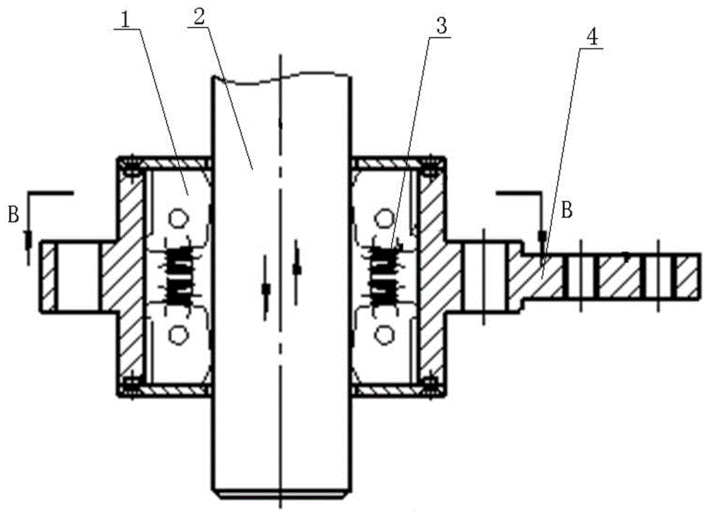
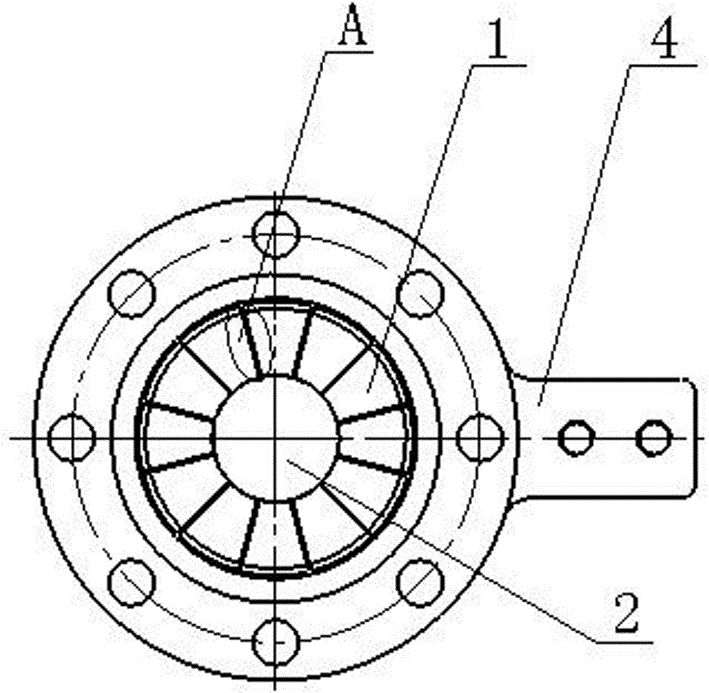
[0026] Embodiment 1 of the wiring board of the present invention: as Figure 1 to Figure 5 As shown, the wiring board includes a wiring board body 4, and the wiring board body 4 is provided with mounting holes for installing conductive contacts. In the mounting holes, upper and lower layers of conductive contacts are arranged along the inner circumference thereof, and each layer of conductive contacts They are all arranged around the center line of the installation hole in the circumferential direction and have a central through hole for the corresponding conductive rod 2 to pass through. Each layer of conductive contact fingers includes a plurality of conductive contact fingers 1, and each conductive contact finger 1 has a The inner wall surface 11 that is electrically connected to the corresponding conductive rod 2, the outer wall surface 12 that is used to contact and electrically connect with the wiring board body 4, and the side surfaces 13 that are respectively arranged o...


PUM


Abstract

The invention relates to a conductive contact finger and a wiring board using the conductive contact finger, comprising a contact surface and a side face opposite to a circumferentially adjacent conductive contact finger, at least one of the two opposite side faces is provided with a convex There are supporting convex parts used to cooperate with the side supports of adjacent conductive contact fingers to maintain the rotation gap between the conductive contact fingers. The present invention adopts the support convex part provided on the side of each conductive contact finger, which can ensure the rotation gap of the adjacent conductive contact fingers in the circumferential direction, so that each conductive contact finger has enough rotation gap to rotate and contact with the conductive rod and the wiring board. Uniform and good contact, accurate resistance value, avoiding damage to corresponding contact parts due to excessive local current.

Description

technical field [0001] The invention relates to a conductive contact finger and a wiring board using the conductive contact finger. Background technique [0002] The wiring board used for conductive connection with the conductive rod in high-voltage circuit products includes the wiring board body. There are mounting holes for assembling the contact fingers on the wiring board body. There are multiple conductive wires in the mounting hole along the circumferential direction of the hole wall. Contact fingers, each conductive contact finger is surrounded by a ring structure with a conductive perforation for the conductive rod to penetrate, and each conductive contact finger has an inner wall surface for contacting the conductive rod and for contacting the wiring board. The outer wall surface of the outer wall and the sides opposite to the adjacent conductive contact fingers on the same circumferential surface, in order to make the conductive contact fingers easier to rotate dur...

Claims


Application Information

Patent Timeline
Patent Type & Authority Patents(China)
IPC IPC(8): H01R13/24H01R9/28
Inventor 张子明贾晓东赵飞刘雅娟
Owner STATE GRID CORP OF CHINA
Why Eureka
Try Eureka